In the textile industry, flame-retardant textiles are being used in an increasingly wide range of applications—from industrial protective workwear and decorative fabrics in public spaces to infant and children’s clothing and vehicle interiors. Their flame-retardant properties directly impact personal safety and environmental safety. This article outlines the testing methods, core standards, and key considerations during the testing process for flame-retardant textiles, providing a reference for industry professionals.
I. Testing Methods for Flame-Retardant Textiles
The core of testing flame-retardant textiles lies in evaluating the fabric’s combustion behavior when exposed to a flame source, including key indicators such as flame spread rate, after-flame time, smoldering time, degree of damage, and smoke emission. Currently, mainstream testing methods are primarily divided into five categories, each tailored to different application scenarios with distinct testing principles and focuses.
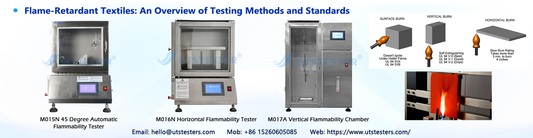
(1) Vertical Burning Test
The vertical burning test is the most commonly used and fundamental flame-retardant testing method, suitable for most apparel textiles, protective clothing, bedding, and similar products. Its core principle is to simulate the combustion characteristics of fabric in a vertically suspended state. The testing principle involves clamping the test specimen vertically in place and applying a standard ignition source (typically a Bunsen burner with a flame height of 40 mm) to the lower edge of the specimen for a specified duration (usually 12 seconds) before removing the flame. The specimen’s after-flame time, smoldering time, and the length of damage after combustion are then recorded to assess the fabric’s flame-retardant performance.
The advantages of this method include its simplicity and broad applicability. It provides an intuitive reflection of the fabric’s flame-retardant performance under actual wearing or hanging conditions, making it the preferred method for factory-exit inspections and routine laboratory testing. Relevant standards include GB/T 5455-2014, ISO 15025, and ASTM D6413, among others; specifications regarding flame height, ignition duration, and pass criteria vary slightly across different standards.
(2) Horizontal Burning Test
The horizontal burning test is primarily suitable for lightweight textiles, decorative fabrics (such as curtains and tablecloths), and plastic-coated fabrics, simulating the burning scenario when the fabric is placed horizontally. The test principle involves placing the specimen horizontally on a specific stand, igniting it from one end with a flame source, observing the spread of the flame, and measuring the flame spread rate and the length of damage. Some standards also require recording whether molten droplets are produced during combustion.
Compared to the vertical burning method, the horizontal burning method places greater emphasis on evaluating a fabric’s flame spread capability when laid flat, making it particularly suitable for textiles that are typically placed horizontally during daily use. Common standards include GB/T 2408-2021, ASTM D635, and ISO 6941. Among these, GB/T 2408-2021 accommodates both vertical and horizontal combustion modes, meeting the testing requirements for a wide range of fabrics.
(3) 45-Degree Combustion Method
The 45-degree combustion method is primarily designed for hanging textiles, such as curtains, drapes, and stage curtains. It simulates the combustion characteristics of these fabrics when hung at an angle. The testing principle involves securing the test specimen at a 45-degree angle to the horizontal plane, igniting it from the bottom, measuring the burn time and extent of damage, and evaluating the flame spread rate along the inclined surface of the fabric.
This method closely mirrors the actual usage scenarios of hanging textiles, accurately reflecting the diffusion patterns of flames on inclined surfaces and avoiding result discrepancies caused by mismatched testing angles. Common standards include the U.S. NFPA 701 (divided into the stricter Class 1 and the general Class 2) and China’s GB/T 5456-2015. Among these, NFPA 701 serves as the core reference standard for flame-retardant testing of hanging textiles worldwide and is widely used in the inspection of export products.
(4) Limiting Oxygen Index (LOI) Method
The Limiting Oxygen Index (LOI) method is a quantitative testing method suitable for the precise evaluation of textile flame-retardant performance, particularly for quality control during the R&D phase and for high-end products. The testing principle involves placing the sample in an environment of a nitrogen-oxygen mixture and gradually adjusting the oxygen concentration until the minimum oxygen concentration required for the sample to sustain combustion (i.e., the Limiting Oxygen Index, LOI) is determined. A higher value indicates stronger flame-retardant performance of the fabric.
Generally, an LOI ≥ 28% is classified as flame-retardant fabric, while an LOI ≤ 20% indicates flammable fabric. The advantage of this method lies in its precise and quantifiable test results, which provide scientific data support for product development and standard formulation. Relevant standards include the international ISO 4589-2, China’s GB/T 5454-1997, and the U.S. ASTM D2863, among others. This method serves as a crucial testing tool for textile enterprises to enhance product quality.
(5) Supplementary Testing for Special Applications
In addition to the four basic methods described above, flame-retardant textiles intended for special applications must undergo specific testing:
1. Smoke Density Testing: Simulates the smoke emission from burning fabrics in enclosed spaces (such as subways and airplanes). Smoke density (Ds value) is measured using the light attenuation method to prevent asphyxiation caused by smoke during a fire. Common standards include GB/T 8627-2007 and ISO 5659-2;
2. Thermal Radiation Test: Designed for industrial protective clothing and fabrics used in high-temperature environments, this test simulates high-temperature radiation scenarios to evaluate the fabric’s thermal protection performance (TPP value). Relevant standards include GB 8965.1-2023 and ISO 13506;
3. Wash fastness testing: Evaluates the durability of flame-retardant properties in fabrics after repeated washing. Typically, fabrics are processed according to the washing procedures specified in GB/T 8629-2017, followed by basic flame-retardant testing to ensure the fabric remains compliant even after long-term use;
4. Smoke toxicity testing: For interior fabrics used in buildings and vehicles, this test measures the release of toxic gases during combustion to prevent secondary harm. Common standards include GB/T 20284-2006 and BS 6853.
II. Standards for Flame-Retardant Textiles
(1) GB Series
GB/T 17591-2025, implemented in 2025, is the latest core standard. It replaces the 2006 edition and further refines testing criteria and classification requirements.
1. GB/T 17591-2025 “Flame-Retardant Fabrics”: A core recommended standard covering flame-retardant fabrics for apparel, decoration, and industrial use. It introduces eight new terms, including burn length, smoke density, and thermal protection performance values. It adjusts test items and performance requirements for different applications—such as interior decoration, vehicle interiors, and flame-retardant protective clothing—including the addition of Class B3 requirements for interior decoration fabrics and smoke density grading for automotive interior fabrics.
2. GB/T 5455-2014 “Textiles—Flame Resistance—Determination of Vertical Burn Length, Smoldering Time, and Afterglow Time”: A recommended standard corresponding to the vertical burning method, applicable to routine flame-retardant testing of various textiles. It specifies sample preparation, testing procedures, and acceptance criteria, and is a commonly used standard for factory-exit testing;
3. GB 8965.1-2023 “Protective Clothing—Flame-Retardant Protection—Part 1: Flame-Retardant Clothing”: A mandatory standard for industrial flame-retardant protective clothing. It specifies test items such as vertical burning and thermal radiation, introduces new Class B2 and B3 requirements, and adjusts metrics such as burn length and after-flame time. It applies to protective workwear used in open-flame and high-temperature environments, such as firefighter uniforms and welding workwear;
4. GB 31701-2015 “Technical Specifications for the Safety of Textile Products for Infants and Children”: A mandatory standard for infant and children’s clothing. It requires flame-retardant performance to meet Class B standards (burn length ≤ 200 mm, after-flame time ≤ 5 s) and strictly prohibits the use of flammable fabrics to ensure children’s safety;
5. GB 8624-2012 “Classification of Fire Performance of Building Materials and Products”: Applicable to flame-retardant textiles used in construction (such as curtains and carpets), this standard classifies fire performance into four levels: A (non-combustible), B1 (difficult to ignite), B2 (combustible), and B3 (flammable), and specifies the testing requirements and acceptance criteria for each level.
(2) International and Regional Standards
1. ISO Series Standards (Internationally Recognized): Core standards include ISO 4589-2 (Limiting Oxygen Index Method), ISO 6940 (Vertical Burning), ISO 6941 (Horizontal Burning), and ISO 15025 (Vertical Burning, applicable to apparel fabrics), with relatively universal performance requirements;
2. ASTM Series Standards (U.S. Standards): Published by the American Society for Testing and Materials (ASTM), these standards are highly targeted. Commonly used standards include ASTM D6413 (Vertical Burning of Textiles), ASTM D3801 (Flame Retardancy of Children’s Sleepwear), ASTM E84 (Smoke Density of Textiles for Construction), and ASTM F1959 (Arc Flash Protection Testing). Among these, 16 CFR 1615/1616 is the mandatory flame retardancy standard for children’s sleepwear, with extremely strict requirements: it must pass the vertical burning test with a burn length ≤ 17.8 cm;
3. EN Series Standards (European Union Standards): Unified European standards applicable to products sold in the EU market. Key standards include EN 13501-1 (classification of combustion performance of construction products, rated from Class A to Class F based on a combined assessment of smoke generation and melting droplets), EN ISO 11925-2 (small flame test), and EN 13773 (curtain fabrics). These standards impose more detailed requirements regarding smoke density and toxic gas emissions, which companies exporting to the EU must strictly adhere to;
4. Standards for Other Regions: The UK BS series (BS 5852 for flame-retardant testing of furniture fabrics, BS EN 11611 for welding protective clothing) and the Japanese JIS series (JIS L 1091 for flame-retardant testing of textiles). Select the appropriate standards based on the requirements of the target market.
III. Applicable Scenarios and Precautions
(1) Selection of Applicable Scenarios
1. Worn textiles (clothing, sleepwear): The vertical burning test (GB/T 5455, ASTM D6413) should be prioritized. Children’s clothing must additionally comply with mandatory standards such as GB 31701 and 16 CFR 1615/1616;
2. Hanging decorative fabrics (curtains, drapes): Prioritize the 45-degree burn test (NFPA 701, GB/T 5456). Fabrics for architectural use must also meet the classification requirements of GB 8624 and EN 13501-1;
3. Industrial protective clothing: Select the vertical burn test combined with thermal radiation testing (GB 8965.1, ASTM F1959) to ensure protective performance in high-temperature and open-flame environments;
4. Vehicle interiors (automobiles, aircraft, trains): Combine the vertical burning test, smoke density test, and smoke toxicity test to comply with standards such as GB/T 17591-2025 and EN 45545-2; for aircraft and train interior fabrics, additional smoke density rating assessments are required;
5. Product R&D/High-End Customization: Prioritize the limiting oxygen index method (ISO 4589-2, GB/T 5454) to precisely quantify flame-retardant performance and optimize product formulations.
(2) Key Testing Considerations
1. Sample Preparation: Samples must be representative, drawn from different batches and locations, and meet standard dimensional requirements; They must also undergo standard pre-treatment (e.g., conditioning) to ensure the samples are in a stable state;
2. Environmental Control: Test environment temperature and humidity must comply with standard specifications;
3. Equipment Calibration: Testing instruments (e.g., combustion testers, oxygen index analyzers) must be calibrated regularly to ensure the accuracy of parameters such as flame height, oxygen concentration, and temperature measurements;
IV. The Importance of Flame Retardant Testing Instruments
Professional flame retardant testing instruments must be compatible with various testing methods and standards. They can accurately measure key indicators such as after-flame time, smoldering time, limiting oxygen index, and smoke density. Characterized by ease of operation, data accuracy, and high stability, these instruments not only meet the needs of enterprises for factory-exit inspections and R&D testing but also provide reliable testing equipment support for third-party testing institutions.
Email: hello@utstesters.com
Direct: + 86 152 6060 5085
Tel: +86-596-7686689
Web: www.utstesters.com