头部背景图片

Julong Cutter Suction Dredger Modular Design for Seamless Dredging & Sand Mining

2026-04-14

The Julong cutter suction dredger is an important product series in the field of water environmental engineering equipment in China, produced by Julong company. This series of dredgers adopts a split structure design, which is easy to disassemble and transport, and has the characteristics of reasonable design, simple operation, strong durability, and strong work continuity. ‌

1. Dredger Overview and Working Principle

The cutter suction dredger /sand dredger is an underwater excavation machinery widely used in port, waterway dredging, and reclamation projects. Its working principle is to use a cutter installed at the front end of the cutter holder to crush the mud and stones at the bottom of the water, forming a mixture of mud and water (slurry). Subsequently, the mud is sucked in from the suction head at the front end of the cutter holder through a centrifugal mud pump, transported through the dredger's suction pipe, mud pump, and mud discharge pipe, and discharged to the designated mud discharge location. The work processes of dredging, transporting and unloading mud or sand can be completed continuously in one time, making it an efficient and low-cost dredging equipment. ‌

2. Application Fields

The JuLong cutter suction dredger is suitable for various operational scenarios, including maintenance dredging, infrastructure dredging, environmental dredging, and sand mining. ‌

The specific adaptation conditions cover dredging and sand excavation operations in water bodies such as ports, lakes, inland rivers, and reservoirs. ‌

If you have dredging project, please feel free to consult us, then we will help you choose suitable dredger machine

Who We Are?

2026-04-14

Qingzhou Golden JuLong Equipment Manufacturing Co., Ltd. specializes in advanced dredgers, amphibious excavator, water cleaning boat, working platform, etc with 38 years of experience in design, production, supply, and maintenance. We hold China ISO certifications, international certifications including BV, RINA, RS, and EU CE.

Julong offers one-stop, customized solutions for different dredging conditions, backed by professional design, skilled welding, field service, and reliable after-sales support.

Our products are exported to over 90 countries across Asia, South America, Oceania, Africa, and Eastern Europe, earning global recognition for advanced technology, high-quality equipment, and trustworthy management. 

Detailed Explanation of the UL94 Flame Retardancy Standard

2026-04-10

UL94 (Standard for Safety of Flammability of Plastic Materials for Parts in Devices and Appliances) is a safety standard for flame retardancy of plastic materials developed by Underwriters Laboratories (UL) in the United States. Widely used in the electronics, automotive, and construction industries, it serves as the core basis for evaluating the combustion behavior of plastic parts in flame environments. Its test results and grading are crucial for material selection and product compliance.


1. UL94 Test Types

The UL94 standard uses different test methods to simulate the burning conditions of materials in actual use. It is divided into two main categories: horizontal and vertical burning tests. These tests are designed for plastic materials of varying thicknesses and application scenarios.

1. Horizontal Burning Test (HB Grade Test)

Scope of Application: Primarily for plastic materials with a thickness of ≤13mm, this test evaluates the burning speed of the material when placed horizontally. This is the lowest level of flame retardancy in the UL94 standard.


Test Procedure:

Prepare the sample to standard dimensions (125mm long x 13mm wide x 3-13mm thick) and secure it horizontally on a stand. Mark the "start line" on one end of the sample (25mm from the ignition end) and the "end line" on the other end (100mm from the start line).

Use a Bunsen burner (20mm flame height, blue flame) to ignite the sample at the ignition end for 30 seconds, then remove the flame.

Observe the sample's combustion behavior: If the flame extinguishes, record the "afterflame time"; if the flame continues to burn to the end line, record the "burning rate."


Acceptance Requirements:

If the flame does not reach the cutoff line and the afterflame lasts ≤ 30 seconds, the test is considered acceptable.

If the flame reaches the cutoff line, the burning speed must meet the following requirements: For thickness ≥ 3mm, the burning speed must be ≤ 40mm/min; for thickness < 3mm, the burning speed must be ≤ 70mm/min.


2. Vertical Flame Test (V-0, V-1, V-2)

Scope of Application: This test is designed for plastic materials with higher flame retardancy requirements (such as internal components and housings of electronic appliances). It evaluates key indicators such as the extinguishing speed and dripping flammability of the material after being ignited by a flame when placed vertically. This is the most widely used test type in UL94.


Test Procedure:

Prepare the sample to standard dimensions (125mm long x 13mm wide x 0.8-13mm thick) and secure it vertically on a stand. Place a layer of dry medical cotton wool 300mm below the sample (to test for ignition of any dripping material).

Light a Bunsen burner (12.7mm blue flame) at the center of the lower end of the sample for 10 seconds. Remove the flame and record the "first afterflame time" and "afterglow time" (the duration of the material remaining red after the flame extinguishes).

After the sample's afterflame and afterglow have completely extinguished, relight the sample with the Bunsen burner for 10 seconds. Remove the flame and record the "second afterflame time" and "second afterglow time."


II. Key Points in UL94 Testing


Influence of Sample Thickness: UL94 ratings are strongly correlated with sample thickness. For the same material, thicker thickness may result in a higher flame retardancy rating (for example, a plastic that achieves V-0 at 3mm may only achieve V-2 at 1mm). Therefore, test reports must clearly indicate sample thickness, and ratings cannot be applied across thicknesses.


Test Environment Requirements: Testing must be conducted in a standard environment (temperature 23±2°C, relative humidity 50±5%). Ambient temperature and humidity can affect the material's combustion behavior (for example, high humidity can reduce combustion speed) and must be strictly controlled.

Grade priority: The UL94 grades, from high to low, are roughly: 5VA > 5VB > V-0 > V-1 > V-2 > HB. The actual selection should be based on the product usage scenario (such as whether it is near a fire source or whether there is a risk of dripping), rather than blindly pursuing the highest grade.


III. Application of the UL94 Standard

Electronic and electrical applications: Components such as charger casings, circuit board substrates, and wire insulation typically require a V-0 or V-1 rating to prevent the spread of fire or the ignition of other components by dripping materials.

Automotive: Interior plastic components (such as instrument panels and door panels) must comply with UL94 V-2 or higher, with some high-temperature areas (such as those around the engine) requiring a 5VA rating.

Construction: Plastic pipes and decorative materials require a comprehensive assessment based on the UL94 rating and local building fire protection standards (such as China's GB 8624).


Email: hello@utstesters.com

Direct: + 86 152 6060 5085

Tel: +86-596-7686689

Web: www.utstesters.com


How Does Tensile Strength Testing Extend the Service Life of Industrial Rubber Products?

2026-04-10

In the field of industrial manufacturing, rubber products are widely used in core sectors such as automotive manufacturing, construction machinery, mining machinery, and aerospace due to their excellent elasticity, wear resistance, and corrosion resistance. From seals and conveyor belts to hoses and shock-absorbing pads, every type of rubber component performs critical functions in connection, cushioning, or transmission. However, industrial environments are complex and ever-changing. Factors such as extreme temperatures, high-pressure friction, and chemical corrosion constantly push rubber products to their performance limits. As one of the core tests for evaluating rubber material performance, tensile strength testing not only assesses rubber quality but also serves as a critical technical means to control product quality at the source and precisely extend service life.


I. What Is Rubber Tensile Strength

Tensile strength refers to the maximum tensile stress a rubber material can withstand before breaking under uniform tension, typically measured in MPa (megapascals). It directly reflects a rubber material’s ability to resist tensile failure caused by external forces and serves as an indicator of its physical and mechanical properties. The magnitude of this value directly determines the durability and reliability of rubber products under actual operating conditions.

From a material perspective, the tensile strength of industrial rubber stems from the cross-linked network of its molecular structure. Natural rubber and synthetic rubbers (such as styrene-butadiene rubber, polybutadiene rubber, and chloroprene rubber) form a three-dimensional network structure through vulcanization. Intermolecular forces and chemical bonds work together to impart elasticity and tensile strength to the rubber. When tensile strength is insufficient, rubber products are highly prone to localized cracking, overall fracture, and other issues when subjected to slight stretching, pulling, or repeated deformation, leading to premature failure. Conversely, excellent tensile strength enables rubber products to stably withstand external forces under complex operating conditions, maintaining their shape and functionality over the long term.


II. Tensile Strength Testing: Principles, Process, and Key Indicators

Tensile strength testing is a standardized process that uses specialized testing equipment to simulate the actual stress conditions experienced by rubber products and quantify their tensile performance. It is primarily conducted using a universal testing machine (also known as a tensile testing machine). The entire process strictly adheres to industry standards such as GB/T 528-2009 “Determination of Tensile Stress-Strain Properties of Vulcanized Rubber or Thermoplastic Rubber” and ISO 37 to ensure the accuracy and comparability of the data.

(1) Sample Preparation

1. Sample Cutting: In accordance with standard requirements, rubber materials are cut into test specimens that meet specified dimensions. Common shapes include dumbbell-type specimens (such as Type 1 and Type 2). The width and thickness of the parallel section in the middle of the specimen must be uniform, and the specimen must be free of defects such as bubbles, cracks, or impurities; otherwise, this may lead to deviations in test data.

2. Environmental Conditioning: Rubber properties are significantly affected by temperature and humidity. Testing must be conducted under standard environmental conditions (temperature 23°C ± 2°C, relative humidity 50% ± 5%) to avoid interference from extreme conditions.

3. Instrument Calibration: Calibrate the universal testing machine’s force transducer and tensile speed in advance to ensure measurement accuracy meets requirements (typically force accuracy ≤ ±0.5%).


(2) Testing Procedure

1. Specimen Installation: Secure both ends of the prepared rubber specimen in the upper and lower grips of the testing machine, ensuring the specimen is centered within the grips to prevent uneven stress distribution caused by skewed clamping.

2. Parameter Setup: Set the tensile speed based on the actual application scenario of the rubber product (the standard testing speed for rubber is 500 mm/min, but this can be adjusted for special conditions), then start the testing machine.

3. Data Acquisition: The testing machine uses sensors to record the tensile force and deformation of the specimen in real time throughout the tensile process until the specimen completely breaks. The system automatically generates a force-displacement curve, with key data including tensile strength, elongation at break, and elastic modulus.


(3) Key Indicators

1. Tensile Strength: Directly reflects the tensile limit of the rubber and is the core indicator for determining whether the product meets operational requirements.

2. Elongation at Break: The percentage of the original gauge length that the rubber specimen stretches before breaking, reflecting the rubber’s ductility.

3. Modulus of Elasticity: The ratio of stress to strain during the initial stage of tensile testing, reflecting the rubber’s stiffness.


III. How Does Tensile Strength Testing Accurately Extend the Service Life of Rubber Products?

(1) Design Phase

Product design is the foundation for determining service life, and tensile strength testing provides critical data for rubber material and formulation design.

- Prevent Performance Deficiencies: If tensile strength testing is not conducted during the design phase and low-strength rubber materials are selected without proper evaluation, the product may fail prematurely during actual use.

- Avoiding Over-Engineering: An excessive pursuit of high tensile strength may increase the cost of the rubber formulation, complicate processing, and even compromise other properties such as elasticity and abrasion resistance.

Additionally, tensile strength test data can assist in optimizing product structural design. By testing the tensile strength distribution under different structural designs, structural curvature and thickness can be optimized to reduce localized stress concentration, thereby enhancing the product’s resistance to tensile failure from a structural perspective.


(2) Production Stage

During rubber production, factors such as the vulcanization process, raw material ratios, and processing precision directly influence the formation of the rubber molecular cross-linking network, thereby altering tensile strength. Tensile strength testing serves as a “quality control checkpoint” in the production process, enabling process optimization and performance stability.

- Vulcanization Process Optimization: Vulcanization time, temperature, and pressure are key determinants of rubber cross-linking density. Insufficient vulcanization results in incomplete cross-linking of rubber molecules, leading to low tensile strength; over-vulcanization, with excessively high cross-linking density, causes the rubber to become brittle. Although tensile strength may increase, the elongation at break decreases significantly, making the material prone to brittle fracture. By conducting regular tensile strength tests on production batches, optimal vulcanization parameters can be precisely determined, ensuring consistent tensile performance across every batch.

- Raw Material Formulation Control: The ratio of different rubber raw materials and additives (such as carbon black and vulcanizing agents) significantly affects tensile strength. Through tensile strength testing, raw material formulations can be optimized to find the optimal balance between “strength, processability, and cost,” thereby avoiding product performance fluctuations caused by formulation errors.


(3) Application Stage

- Static Tensile Applications (e.g., pipe sealing gaskets): Focus on tensile strength and long-term deformation performance to prevent rubber fatigue and aging caused by prolonged tension;

- Dynamic Tensile Applications (e.g., automotive hoses, rubber springs for vibrating screens): Balance tensile strength, elongation at break, and fatigue resistance to select rubber materials suitable for dynamic operating conditions through testing.

- Service Life Prediction and Maintenance: By continuously monitoring changes in tensile strength during the service life of rubber products, service life prediction models can be established.


(4) Aging Protection

Industrial rubber exposed to external environments over extended periods may experience issues such as reduced tensile strength and loss of elasticity due to thermal-oxidative aging, ozone aging, and chemical corrosion. Tensile strength testing can be used to evaluate the rubber’s resistance to aging and guide the development of protective measures.

- Screening of Anti-Aging Materials: By comparing the aging rates of tensile strength in rubber after adding different anti-aging additives (such as antioxidants and ozone protectants), long-lasting anti-aging formulations can be identified.

- Optimization of Protection Strategies: For special operating conditions such as high temperatures and high corrosion, tensile strength testing can be used to evaluate the adhesion performance of different protective layers (e.g., anti-corrosion coatings, metal cladding) to the rubber substrate. This ensures that the protective layers do not peel off, providing continuous protection against external erosion and delaying the deterioration of tensile properties.

Tensile Strength Tester


Email: hello@utstesters.com

Direct: + 86 152 6060 5085

Tel: +86-596-7686689

Web: www.utstesters.com


How to Ensure Color Fastness in High-Performance Outdoor Fabrics?

2026-04-10

Introduction

In the field of outdoor apparel and gear, color fastness is one of the core indicators for measuring product quality. A high-quality jacket, tent, or outdoor backpack must not only possess functional properties such as waterproofing, breathability, and abrasion resistance, but also retain its vibrant colors after prolonged exposure to sun and rain, frequent washing, and repeated friction. Products with poor colorfastness not only compromise aesthetics but may also pose health risks as dye molecules can migrate through the skin.

I. Colorfastness Testing Parameters for Outdoor Fabrics

According to industry standards such as GB/T 32614-2016 “Outdoor Sportswear—Jackets,” high-performance outdoor fabrics must undergo rigorous testing for the following colorfastness parameters:

1. Lightfastness

Since outdoor products are exposed to UV radiation for extended periods, lightfastness is the primary evaluation criterion. According to GB/T 8427-2019 “Textiles—Color Fastness Tests—Color Fastness to Artificial Light: Xenon Arc,” the lightfastness of outdoor functional fabrics is typically required to reach Level 4 or higher, with high-end products needing to achieve Levels 5–6.

Test Method: Place the test sample alongside a blue wool standard fabric under a xenon arc lamp or carbon arc lamp. The grade is determined by comparing the degree of color change (1–8, with 8 being the best).

2. Wash Fastness

Outdoor apparel requires frequent washing to remove sweat stains and dirt. According to GB/T 3921-2008 “Textiles—Color Fastness Tests—Soap Wash Fastness,” infant and children’s clothing must have a wash fastness (color change) of ≥4, while outdoor functional fabrics, due to harsher usage environments, typically require a rating of 4–5.

Test Method: Sew the test sample to a standard backing fabric, then wash it under specific conditions (typically at 40–60°C, with a specific detergent concentration and mechanical agitation) to evaluate the degree of color change and color transfer.

3. Rubbing Color Fastness

During outdoor activities, fabrics frequently rub against backpacks, rocks, and equipment, making areas prone to friction—such as collars, cuffs, and the seat—particularly susceptible to color loss. According to standard requirements, the rubbing color fastness of outdoor fabrics must be ≥ Grade 4 for dry rubbing and ≥ Grade 3 for wet rubbing.

Test Method: Using a color fastness to rubbing tester, the sample is subjected to a specified number of back-and-forth rubs with dry/wet rubbing cloths under standard pressure, and the results are graded using a gray scale (1–5).

4. Perspiration Fastness

During outdoor activities, heavy sweating occurs, and acidic or alkaline substances in sweat can accelerate dye leaching. According to GB/T 3922-2013, both acid sweat fastness and alkaline sweat fastness must be tested separately.

5. Water/Seawater Fastness

For water sports equipment and swimwear, water fastness (GB/T 5713) and seawater fastness (ISO 105-E02) must also be tested to ensure the fabric does not fade or bleed in wet conditions.


II. Factors Affecting the Color Fastness of Outdoor Fabrics

1. Choice of Dyes

The manner in which dyes bond with fibers directly determines the level of color fastness:

- Reactive dyes: Suitable for cellulose fibers such as cotton and linen; they produce vivid colors but have relatively poor wet rubbing fastness

- Disperse Dyes: Suitable for synthetic fibers such as polyester; require high-temperature, high-pressure dyeing

- Reducer Dyes: The dye becomes insoluble in water after fixation, offering better wet-rub fastness than reactive dyes

- Solution Dyeing: Color masterbatches are added while the fiber is in a molten state; this method provides the best color fastness and is particularly suitable for outdoor applications involving prolonged exposure to sunlight

2. Dyeing Process

- Temperature Control: For dark-colored fabrics, the dyeing temperature may be appropriately increased, but the heating rate must be strictly controlled to prevent uneven dyeing

- Holding Time: Dark-colored fabrics require extended holding times to ensure thorough dye-fiber bonding

- pH Management: Different dyes have optimal pH ranges for dye uptake, which must be precisely controlled

3. Use of Auxiliaries

- Retarders: Dosage must be strictly controlled; excessive amounts will reduce dye uptake and binding strength

- Fixatives: Proper use can improve colorfastness by 0.5–1 grades, but attention must be paid to the compatibility between the fixative type and the dye

- Softeners: Used during the finishing stage, but may react with dyes and reduce colorfastness; dosage must be just right

4. Post-Dyeing Washing

After dyeing, thorough soap washing and rinsing must be performed to ensure the removal of excess dye from the fabric surface. Insufficient washing temperature or duration will result in residual excess dye, severely affecting the final colorfastness.


III. Strategies for Improving Color Fastness in Outdoor Fabrics

Strategy 1:

For products exposed to prolonged outdoor sunlight (such as awnings, boat covers, and outdoor furniture fabrics), we recommend using solution-dyed polyester or nylon fibers. This technique involves adding color masterbatches during the polymer melting stage, making the color an integral part of the fiber and providing exceptional lightfastness and weather resistance.

Strategy 2:

1. Thorough pretreatment: Ensure the fabric is thoroughly desized, scoured, and bleached to create a uniform base for dyeing.

2. Batch addition: For dark-colored fabrics, add auxiliaries and dyes in separate batches to improve absorption.

3. Strict fixation: Control the amount of fixing agent (typically 2–4%), temperature (50–60°C), and time (20–30 minutes).

4. Thorough rinsing: Use a progressive rinsing process, starting with warm water, followed by soapy water, and finally a clear water rinse

Strategy 3

Outdoor fabrics often require functional finishes such as waterproofing, stain resistance, and antimicrobial treatments, but these finishes may react with the dyes. Recommendations:

- Select functional finishes with good compatibility with the dyes

- Control the dosage of finishing agents to avoid excessive cross-linking, which can lead to a stiff handfeel and reduced colorfastness

- For dark-colored fabrics, it is recommended to conduct small-batch trials first to assess the impact on colorfastness


IV. Professional Textile Testing Instruments

- Lightfastness tester: Complies with GB/T 8427 and ISO 105-B02 standards, equipped with a xenon arc light source

- Wash Fastness Tester: Supports multiple washing programs with temperature control accuracy of ±1°C

- Rub Fastness Tester: Capable of dry/wet rubbing tests with adjustable pressure and stroke

- Sweat Fastness Tester: Supports acid/alkaline sweat tests, compliant with GB/T 3922 requirements

For more information on textile testing solutions, please contact the UTSTESTER technical team.

color fastness to rubbing tester


Email: hello@utstesters.com

Direct: + 86 152 6060 5085

Tel: +86-596-7686689

Web: www.utstesters.com


How to Measure the Slip Resistance and Durability of Safety Shoes?

2026-04-10

In the field of industrial safety, a pair of compliant safety shoes not only provides a comfortable wearing experience but also serves as a vital line of defense for protecting workers’ lives. Excessive sole wear is the primary cause of reduced protective performance. This article will provide a detailed overview of professional testing methods for assessing the slip resistance and durability of safety shoes.


I. Slip Resistance Testing

1.1 Why Is Slip Resistance Testing Critical?

Slip resistance is one of the core safety indicators for safety shoes. On wet, oily, or slippery surfaces, the sole’s coefficient of friction directly determines whether the wearer is prone to slipping. According to the requirements of international standards ISO 20345:2022 and EN ISO 20347:2022, safety shoes must pass rigorous slip resistance rating tests to be labeled with the slip resistance (SR) rating on the product.


1.2 Testing Standards

ISO 13287:2019: Test methods for slip resistance of footwear for personal protective equipment, covering inclined platform and coefficient of friction tests

ASTM F2913-2019: Standard test methods for slip resistance of footwear, measuring static and dynamic coefficients of friction on dry and wet surfaces

GB/T 20991-2007: Test Methods for Slip Resistance of Footwear for Personal Protective Equipment

EN ISO 20344:2021: Test Methods for Footwear for Personal Protective Equipment, including requirements for slip resistance testing


1.3 Detailed Test Methods

Method A: Horizontal Traction Method (Coefficient of Friction Test)

This is the most commonly used laboratory test method:

1. Sample Preparation: Secure the entire shoe or sole sample to the test platform

2. Test Surface: Use standard ceramic tiles, stainless steel plates, or flooring materials simulating actual working conditions

3. Surface Conditions: Test on dry surfaces, wet surfaces, and oil-water mixed surfaces (NALS lubricant)

4. Test Procedure: Pull the specimen at a constant speed and measure the friction force between the sole and the test surface

5. Result Calculation: Coefficient of Friction (COF) = Friction Force / Vertical Load

Passing Criteria (based on EN ISO 20345:2022):

1. Ceramic tile + water + NALS surface: Coefficient of friction ≥ 0.19 when the heel is tilted 7°; ≥ 0.22 when the forefoot is tilted 7°

2. Ceramic tile + glycerin surface: Coefficient of friction ≥ 0.31 when the heel is tilted 7°; ≥ 0.36 when the forefoot is tilted 7°


Method B: Inclined Platform Method (Slope Test)

Simulating real-world walking conditions:

- Place the test subject (or mechanical simulator) on an adjustable-angle platform

- Cover the platform surface with standard test materials (ceramic tiles, steel plates, etc.)

- Gradually increase the incline angle until slippage occurs

- Record the critical slippage angle; a larger angle indicates better slip resistance


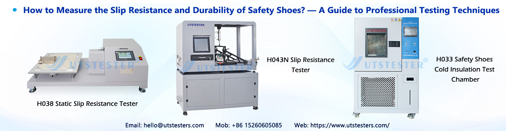
1.4 Professional Testing Equipment

Modern anti-slip testing primarily relies on the following equipment:

1. Coefficient of friction tester: Equipped with a high-precision force sensor capable of recording changes in friction in real time

2. Inclined anti-slip tester: Compliant with ISO 13287 standards, automatically adjusts the incline angle

3. Environmental control chamber: Ensures testing is conducted under standard temperature and humidity conditions (23°C ± 2°C, 50% ± 5% RH)


II. Durability Testing: Assessing the “Longevity” of the Outsole


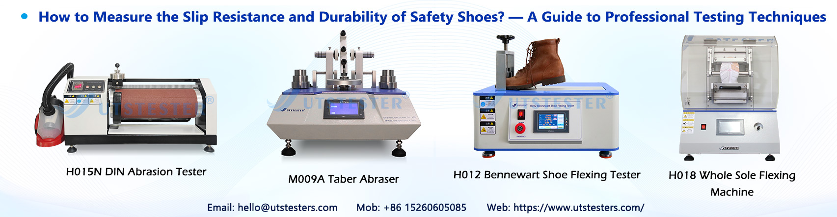
2.1 Abrasion Resistance Testing—The “Marathon” for Outsole Materials

Abrasion resistance is a key indicator for measuring the service life of outsole materials. In accordance with the GB/T 3903.2-2008 and ISO 4649:2017 standards, the rotating drum abrasion test method is primarily used.

XM Abrasion Method (GB Method)

This is the most commonly used method in Chinese safety shoe testing:

Test Parameters:

- Abrasive wheel specifications: Diameter (20±0.1) mm × Width (4±0.1) mm, 72 teeth, T12 steel

- Abrasive wheel speed: (191±5) r/min

- Test load: 4.9 N

- Test duration: 20 minutes of continuous abrasion

Result classification:

- First-class product: Abrasion mark length < 10 mm

- Acceptable product: Abrasion mark length < 13 mm


DIN Abrasion Test (DIN 53516)

Widely used for testing rubber soles:

- A rotating abrasive wheel is used to rub the test specimen under a specific pressure

- Test results are expressed as the volume of material removed (mm³)

- Standard shoe soles are considered合格 if wear volume ≤ 100 mm³/1.61 km

- Safety shoes have stricter requirements, typically ≤ 80 mm³


Taber Abrasion Test (ASTM D3884)

Suitable for various sole materials:

- Uses a Taber abrasion tester equipped with an H-18 or CS-17 wheel

- Test cycles are typically 1,000 or customizable

- Evaluates mass loss or changes in thickness


2.2 Flex Resistance Testing — Simulating Walking Fatigue

Soles undergo repeated bending during walking; flex resistance testing simulates this process:

Test standards: ISO 17707, EN ISO 20344

Test Procedure:

1. Secure the sole specimen to the flexing tester

2. Perform repeated flexing at a specific angle (typically 90°) and frequency

3. The test cycle typically consists of tens of thousands of cycles (e.g., 30,000 or 50,000 cycles)

4. Inspect the sole for cracks, fractures, or delamination

Passing Criteria: No through cracks in the sole after testing; peel strength retention ≥80%


2.3 Full Shoe Durability Testing — Real-World Simulation

In addition to material-level testing, full shoe testing better reflects actual usage conditions:

SATRA TM144 Full Shoe Abrasion Test (EU CE Certification Requirement):

- Simulates human walking with a 10 km continuous walking test

- Post-test requirements: Sole tread depth ≥ 1 mm, and slip resistance (COF) ≥ 0.4

- Applicable for professional certification of safety shoes and protective footwear


ISO 20344 Full Shoe Abrasion Test:

- No sole exposure after 20 km of walking

- Thickness retention rate ≥ 70%


III. How to Select the Appropriate Testing Solution?

Select test items based on the intended use of the footwear

1. Kitchen/Food Industry: Focus on slip resistance on oil-water mixed surfaces

2. Construction Sites: Emphasize abrasion resistance and puncture resistance

3. Electronics Workshops: Require additional anti-static and ESD testing

4. Cold Storage/Low-Temperature Environments: Include low-temperature flexing and slip resistance testing


Email: hello@utstesters.com

Direct: + 86 152 6060 5085

Tel: +86-596-7686689

Web: www.utstesters.com


What is the difference between the hydrostatic head test and the hydrostatic pressure test for textiles?

2026-04-10

In the research, development, and quality control of functional textiles (such as jackets, tents, medical protective clothing, and industrial waterproof fabrics), the evaluation of waterproof performance is a key indicator. The two most common methods are the hydrostatic head test and the hydrostatic pressure test. Although the two appear similar, there are significant differences in their testing objectives, methods, result presentation, and applicable standards. This article provides a systematic explanation.


I. Conceptual Differences Between the Two


1. Hydrostatic Head Test

Metric: The maximum height of a water column that the fabric can withstand (expressed in cmH₂O or mmH₂O).

Test Objective: The critical point at which the fabric begins to leak when the water column height reaches a certain value.

Significance: More suitable for describing a material’s “resistance to hydrostatic pressure penetration.”


2. Hydrostatic Pressure Test

Metric: The fabric’s resistance to hydrostatic pressure under sustained pressure conditions.

Test Objective: To evaluate the material’s leak resistance and sustained stability as pressure is maintained or increased.

Significance: Places greater emphasis on the material’s performance under continuous pressure.


II. Differences in Test Principles and Methods


1. Hydrostatic Head Test: Determines the endpoint by gradually increasing the water column height until water seepage or dripping occurs. Suitable for waterproof fabrics and coated fabrics, such as outdoor apparel fabrics, tent fabrics, raincoats, and footwear materials;

2. Hydrostatic Pressure Test: Utilizes a pressure system to apply continuous or stepwise pressure; evaluation is based on reaching a specified pressure or the occurrence of leakage. Suitable for medical protective clothing, industrial protective materials, composite membrane materials, and high-strength waterproof materials.


III. Applicable Standards and Industry Applications


Common Standards

ISO 811: Textiles—Determination of water repellency of fabrics—Hydrostatic pressure test

AATCC 127: Textiles—Water Repellency (Hydrostatic Head Method)

GB/T 4744: Textiles—Determination of Water Repellency—Hydrostatic Head Method


Note: Different standards have varying requirements regarding pressure ramp rates, pass/fail criteria, and sample preparation. Testing must strictly adhere to the provisions of the applicable standard.


IV. Interpretation of Results


Hydrostatic Head Test Results (Examples)

5,000 mmH₂O: Generally indicates moderate water resistance

10,000 mmH₂O or higher: Suitable for scenarios with high water resistance requirements (e.g., mountaineering, extreme outdoor activities)


Hydrostatic Pressure Test Results (Examples)

No leakage at 20 kPa: Indicates that the material maintains excellent protective performance under sustained hydrostatic pressure


V. Recommendations for Enterprise Selection


If fabric grade and water resistance classification are priorities: Prioritize a hydrostatic head tester.

If protective performance and sustained pressure stability are priorities: Prioritize a hydrostatic pressure tester.

If a comprehensive evaluation is required: We recommend configuring a comprehensive hydrostatic pressure testing system that supports multiple standards and modes.


VI. Key Considerations for Instrument Configuration

1. Adjustable pressure ramp rate: To meet the requirements of different standards

2. Stable sample clamping: To prevent edge leakage and false positives

3. Automatic leakage detection: To reduce human error

4. Data storage and report generation: To facilitate quality traceability and audits

5. Unit conversion: mmH₂O / kPa / bar


Conclusion


Although “Hydrostatic Head Testing” and “Hydrostatic Testing” have similar names, their application objectives, methods, and the significance of their results differ. Correctly distinguishing between them and selecting the appropriate testing method not only improves testing efficiency but also ensures product performance and compliance in target markets.


If you wish to select a suitable testing solution based on your company’s products, applicable standards, or customer requirements, please contact the UTSTESTER technical team for professional advice and instrument selection support.

hydrostatic head test


Email: hello@utstesters.com

Direct: + 86 152 6060 5085

Tel: +86-596-7686689

Web: www.utstesters.com


Why is breathability testing crucial for athletic apparel performance?

2026-04-10

Breathability directly impacts wearer comfort, particularly in athletic wear and outdoor gear. Breathable fabrics effectively wick away sweat, keeping skin dry to enhance comfort and athletic performance. In athletic apparel design, breathability is a key metric—designers must ensure selected materials provide adequate airflow during intense activity.


I. Definition of Breathability


Breathability refers to the ability of gases to pass through polymers, including films, coatings, and fabrics. “Vapor permeability” specifically denotes the capacity of water vapor to traverse fabrics, also termed “moisture permeability” within the industry. Ensuring comfort requires meeting both air permeability and vapor permeability requirements.

Fabric breathability measures the ability of air to pass through the material. It is tested by creating a pressure differential across the fabric. Specifically, it is the pressure differential across the fabric. It represents the volume of air flowing through a unit area of the fabric per unit time. The common unit is mm/s. Air requires a pressure differential to flow. The fabric must maintain this pressure differential to generate airflow.


II. Testing Principle


When a pressure differential exists across the fabric, air flows through it. Flow rate is the volume of air passing through a unit area of the fabric per unit time. The common unit is mm/s. Because a pressure differential is essential for airflow.

Only a pressure differential enables air movement. Therefore, the fabric on both sides must maintain a certain pressure differential to allow air passage. Breathability impacts fabric comfort. It affects the fabric's thermal insulation and warmth retention. Fabric breathability is crucial for the body. It transfers heat, moisture, and gases like carbon dioxide to the outside.


III. Why Sportswear Requires Breathability


During exercise, the human metabolic rate increases dramatically, generating significant heat and sweat. Data indicates that during high-intensity exercise, the human body can sweat 0.5-2 liters per hour. At this point, the core mission of athletic apparel is to rapidly dissipate heat and expel sweat, maintaining the balance of the “microclimate” between the skin and the garment—the temperature, humidity, and airflow velocity of this microclimate directly determine wearing comfort.

Well-ventilated athletic apparel creates efficient airflow channels, allowing cool external air to enter while expelling warm internal air for effective heat exchange. Simultaneously, moisture-wicking properties rapidly transport sweat from the skin's surface to the outer fabric layer for evaporation, preventing the sticky discomfort caused by sweat buildup. Conversely, poorly breathable garments act like an “airtight barrier,” trapping heat and sweat between skin and fabric. This raises perceived body temperature by 2-3°C, causing intense discomfort and increasing the risk of skin friction injuries.

Breathability testing scientifically quantifies a fabric's air transmission capacity, ensuring clothing maintains its “thermoregulatory” function across varying exercise intensities.


IV. Performance Impact of Apparel Breathability


For professional athletes or enthusiasts pursuing athletic efficiency, breathability not only affects comfort but directly impacts performance. Sports medicine research indicates that insufficient breathability in clothing causes sustained increases in core body temperature, leading to accelerated heart rate and heightened physical exertion. This can reduce exercise endurance by over 18%.

Different athletic scenarios demand varying levels of breathability, and breathability testing enables companies to achieve “precise matching.” For instance: - Polyester fabrics commonly used in running apparel must ensure an air permeability rate ≥120mm/s to manage sustained heat generation; Nylon fabrics for mountaineering apparel must prioritize moisture evaporation rates ≥550g/m²/h to meet sweat management demands in variable outdoor conditions; while elastic garments like yoga wear require testing for breathability changes ≤10% after 20% stretch to ensure stable ventilation during movement.

Additionally, breathability and fabric dynamic adaptability must be validated through testing. Body movements and fabric stretching during exercise alter pore structures. Dynamic breathability testing simulates real-world motion to ensure garments maintain consistent breathability under conditions like stretching and friction, preventing performance degradation due to breathability failure during activity.


V. Apparel Fabric Breathability Testing Instruments


The precision of breathability testing directly relies on specialized testing instruments. High-quality textile testing equipment can simulate various environmental conditions (temperature, humidity, pressure differential) to accurately measure multiple indicators such as air permeability, moisture resistance, and thermal resistance, providing enterprises with comprehensive and reliable performance data.

Digital breathability testers deliver reliable results quickly. They are suitable for breathability testing of various textiles. This includes technical textiles, nonwovens, and other breathable products. It complies with standards such as GB/T5453, GB/T13764, ISO9237, ISO7231, ISO5636, ASTM D737, DIN 53887, JIS L1096, BS5636, and others.

Air flows vertically through the fabric. This creates a pressure difference between the front and back surfaces of the fabric. We measure the airflow rate through the fabric at a set pressure differential. This yields the air permeability value.


Conclusion: Prioritizing Air Permeability Testing to Create Truly “High-Performance Sportswear”


From wear comfort to athletic performance, from health safety to market competitiveness, air permeability is an indispensable core performance characteristic of sportswear. Air permeability testing serves as the “critical link” in ensuring this performance. It not only provides enterprises with precise performance data to support R&D upgrades and quality control but also enables consumers to purchase functional sportswear that genuinely meets their needs.

As a dedicated player in the textile testing instrument field, we remain committed to delivering breathability testing solutions compliant with international and domestic standards. This empowers enterprises to accurately control product breathability performance and enhance their core competitiveness.

Digital breathability testers


Email: hello@utstesters.com

Direct: + 86 152 6060 5085

Tel: +86-596-7686689

Web: www.utstesters.com


How do high and low temperature motors ensure stable operation in extreme environments?

2026-04-03

High and low temperature motors (also called extreme-temperature or specialized-environment motors) are engineered with specific materials, design adaptations, and thermal management strategies to ensure stable, reliable operation in conditions far beyond standard industrial motors (-20°C to +40°C ambient). These motors are used in applications like oil & gas downhole drilling, aerospace, cryogenic systems (e.g., space or superconducting tech), furnaces, and Arctic/industrial extreme environments.

High-Temperature Motors (typically 150°C–260°C+ environments)

High temperatures accelerate insulation degradation, cause thermal expansion issues, demagnetize permanent magnets, reduce lubrication effectiveness, and increase internal heat buildup (every ~10°C above rated temperature halves insulation life).

Key design features for stable operation include:

Advanced insulation systems — Standard varnishes fail above ~150°C. High-temperature motors use Class H (180°C) or proprietary systems (up to 260°C+) with materials like mica, polyimide films, advanced enamels, or exotic non-copper magnet wire coatings to prevent breakdown, short circuits, and thermal runaway.

High-temperature-resistant magnets — Samarium-cobalt (SmCo) or specialized neodymium grades retain magnetism well above 200°C, unlike standard NdFeB magnets that lose strength rapidly.

Core and structural materials — Low-loss electrical steels (e.g., M19/M36 grades) maintain magnetic performance and mechanical strength with minimal core losses at elevated temperatures.

Thermal management and heat dissipation — Enhanced cooling via ribbed housings, improved ventilation, or derating (operating below nominal power). Some designs incorporate active monitoring (RTDs/thermistors) to prevent overheating.

Bearings and lubrication — Dry lubricants or high-temperature greases avoid evaporation/volatilization. Bearings use materials that resist thermal expansion and maintain clearance.

Magnet retention and mechanical integrity — Advanced bonding or sleeving techniques keep magnets secure at high speeds (>100,000 RPM in some cases) and temperatures >200°C.

These adaptations allow stable torque, speed, and efficiency in downhole oil/gas tools, furnace operations, aerospace, and defense systems.

Low-Temperature Motors (cryogenic/extreme cold, typically -50°C to -196°C or lower, e.g., LN₂ at 77 K)

Extreme cold causes material embrittlement (metals/plastics become brittle and crack), contraction (leading to mechanical stress or gaps), lubricant freezing/solidification, increased electrical resistance in normal conductors, and challenges with thermal contraction differences.

Key design features for stable operation include:

Cryogenic-compatible materials — Low-thermal-expansion or ductile-at-low-temp materials (e.g., certain stainless steels, non-magnetic plastics like G-10 glass-reinforced epoxy, or nylon for components). Avoid brittle materials prone to fracture.

Special insulation and windings — Materials that remain flexible and dielectric at cryogenic levels; in superconducting designs, zero-resistance windings (e.g., high-temperature superconductors or conventional at LN₂ temps) enable ultra-high efficiency and power density.

Lubrication solutions — Dry lubrication, special low-temp greases, or no lubrication (e.g., gas bearings, magnetic bearings, or bearingless designs using self-levitation in switched-reluctance motors).

Bearing and mechanical design — Designs accommodate differential contraction (e.g., compliant mounts or precise gap control). Bearingless or active magnetic levitation avoids freezing issues.

Cooling/thermal isolation — In cryogenic environments, motors may use conduction cooling, liquid nitrogen immersion, or vacuum-insulated systems to manage heat loads while preventing excessive boil-off or thermal runaway during operation.

Magnetic and electrical optimization — Some designs exploit improved magnetic properties at low temperatures (higher saturation in cores) for higher power density, especially in space propulsion or superconducting rotating machines.

These features enable reliable performance in space applications, LNG systems, particle accelerators, and superconducting motors/generators.

In both cases, motor companies often perform gradual thermal cycling tests, derate performance, and use finite element analysis to predict behavior. This ensures that catastrophic failure modes (insulation breakdown in heat; embrittlement/cracking in cold) while maintaining torque, efficiency, and longevity.

How Vacuum Stepper Motors Operate in Extreme Environments

2026-04-03

In the world of high-precision motion control, standard motors often fail when removed from the Earth’s atmosphere. Whether in semiconductor fabrication, space exploration, or scientific research, specialized vacuum stepper motors are required to perform precise movements where air is absent.

Understanding how these motors work requires looking beyond basic electromagnetism and into the materials science and thermal management necessary for "airless" operation.

1. The Core Principle: Electromagnetic Stepping

At its heart, a vacuum stepper motor operates on the same fundamental principle as a standard stepper motor. It is a brushless DC motor that divides a full rotation into a number of equal "steps."

The Stator: Contains multiple coils (windings) that, when energized, create an electromagnetic field.

The Rotor: Usually a permanent magnet or a soft iron core with teeth.

The Movement: By energizing the stator coils in a specific sequence, the magnetic field "pulls" the rotor, causing it to align with the field in incremental steps.

2. Overcoming the Vacuum Challenge

While the electromagnetic theory remains the same, a standard motor would quickly seize or fail in a vacuum. Vacuum stepper motors are engineered to overcome three primary hurdles:

A. Outgassing and Material Integrity

In a vacuum, materials like standard plastics, glues, and greases undergo outgassing—a process where trapped gasses are released into the environment. This can contaminate sensitive equipment (like telescope lenses or silicon wafers).

The Solution: Vacuum motors use specialized high-temperature polymers (like Polyimide/Kapton) for wire insulation and stainless steel or aerospace-grade alloys for the housing.

B. Thermal Management (The Absence of Convection)

On Earth, motors stay cool because air moves around them, carrying away heat (convection). In a vacuum, there is no air. Heat can only escape through conduction (through the motor mounts) or radiation.

The Solution: These motors are built with high-efficiency windings to minimize heat generation. They are often "heat-sunk" to a metal plate that conducts thermal energy away from the motor body.

C. Specialized Lubrication

Standard oils and greases evaporate in a vacuum, leading to metal-on-metal friction and eventual welding of the bearings.

The Solution: Vacuum stepper motors utilize solid lubricants (such as molybdenum disulfide or tungsten disulfide) or specialized low-vapor-pressure synthetic fluids that do not evaporate under low pressure.

3. Key Design Modifications

To ensure long-term reliability in environments reaching pressures as low as $10^{-7}$ to $10^{-10}$ hPa (Ultra-High Vacuum), manufacturers implement several critical design changes:

Vented Holes: Small channels are drilled into screw holes and internal cavities. This prevents "virtual leaks," where pockets of air trapped during assembly slowly leak out over weeks, ruining the vacuum levels of the chamber.

Encapsulated Coils: Windings are often vacuum-impregnated with specialized resins to ensure no air bubbles are trapped within the motor's electrical heart.

High-Grade Bearings: Bearings are often made of ceramic or dry-lubricated stainless steel to prevent cold-welding.

4. Summary of Technical Specifications

compare

Conclusion

The vacuum stepper motor is a triumph of specialized engineering. By stripping away materials that outgas and re-engineering how heat and friction are managed, these motors allow for nanometer-scale precision in the most inhospitable environments known to science. Whether it is moving a sample inside an electron microscope or positioning a satellite component, the vacuum stepper motor provides the "steps" necessary for modern technological progress.

Categories
Tags