LEO has secured an order for 31 core pump units in the world's largest coal power carbon capture demonstration project (CCUS).
The World Meteorological Organization (WMO) released its Greenhouse Gas Bulletin, stating that atmospheric carbon dioxide concentrations have reached record highs. To halt Earth's warming, it is imperative to convert CO2 into green energy.
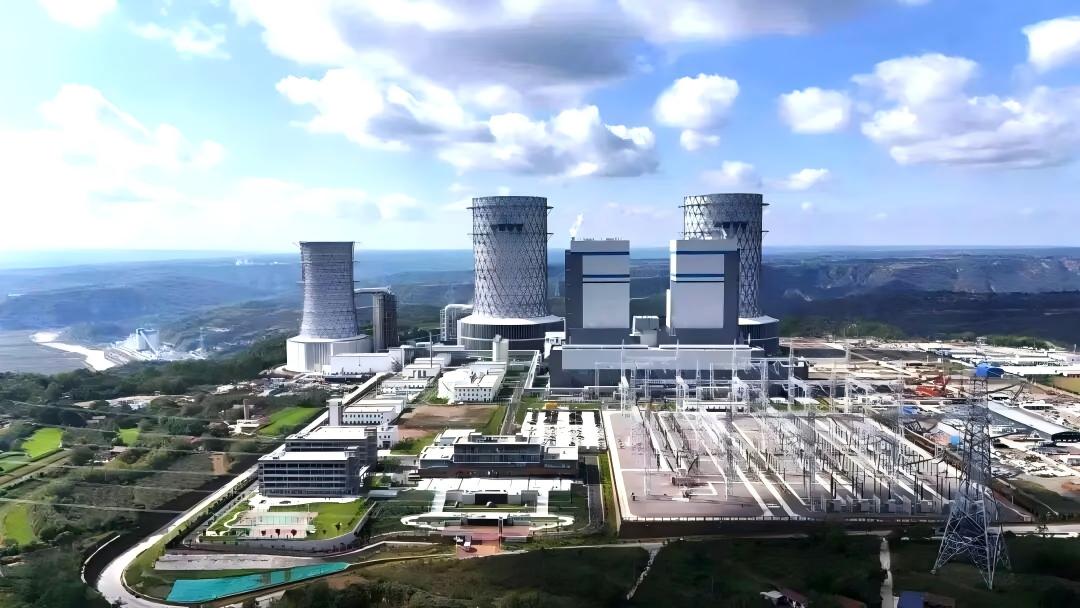
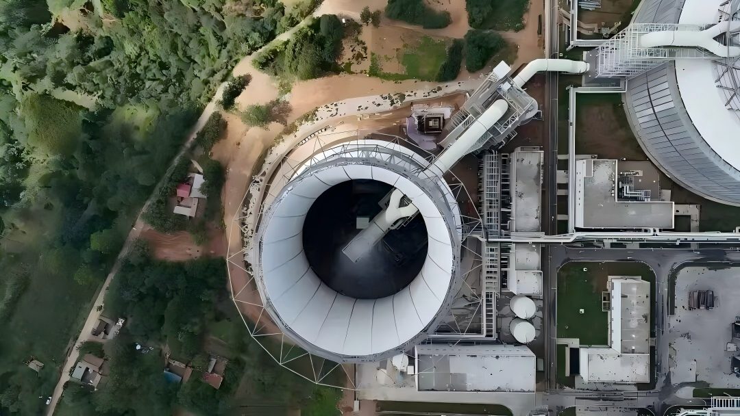
Recently, the world's largest coal power carbon capture demonstration project was officially launched at Huaneng's Zhengning Power Plant in Gansu Province, China. This marks a historic leap for China's CCUS (Carbon Capture, Utilization and Storage) technology, transitioning from' 10,000-ton-scale demonstration 'to' 1-million-ton-scale industrial application'.
The project achieves 100% domestic production of core equipment. Leveraging its deep technical expertise and innovation capabilities, LEO provides customized pumps and integrated system solutions covering the entire process cycle, flue gas scrubbing, and wastewater treatment, establishing itself as a trusted fluid transportation partner for this national-level mega-project.
project context
CCUS (Carbon Capture, Utilization and Storage) is a process that captures carbon dioxide from industrial production, energy use, or the atmosphere, either for reuse or underground storage to achieve permanent emission reduction.
Among these, post-combustion capture technology has emerged as the most prominent technical approach due to its direct integration with existing coal-fired power plant flue gas systems and flexible retrofitting capabilities. However, this technology has long faced core challenges of high energy consumption and substantial costs, leading to its widespread application being once regarded as an "expensive climate solution".
The million-ton CCUS demonstration project at Huaneng Gansu Zhengning Power Plant emerged as a game-changing initiative in this context. As both a national demonstration project and one of the first green low-carbon projects approved by the National Development and Reform Commission (NDRC), it serves not only as the core component of China's first multi-energy complementary integrated energy base—Huaneng Longdong Energy Base—but also carries the strategic mission of advancing CCUS technology from the' lab 'to the' main battlefield'.
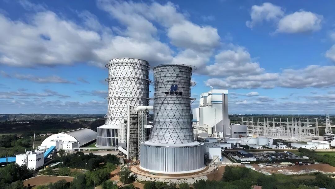
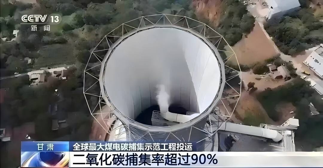
Located in Qingyang City, Gansu Province, this project boasts an annual carbon capture capacity of 1.5 million tons. Utilizing advanced post-combustion chemical absorption technology, it captures over 90% of carbon dioxide from power plant flue gas, yielding a product purity exceeding 99.5%. The project's hourly CO₂ processing volume matches the daily emissions of approximately 18,000 people, while its annual carbon sequestration capacity rivals that of planting 60,000 mu (about 4,000 hectares) of forest in a single year.
Notably, the project has achieved 100% domestic production of its technology and equipment, while innovatively integrating grid peak-shaving capabilities. This provides a practical engineering model for China's exploration of synergistic development between' energy security 'and' green transition ', standing as one of the world's largest coal-fired power CCUS projects.
Project Challenges
The Zhengning million-ton carbon capture system features a complex process flow and extreme medium conditions, imposing near-imposing reliability requirements on the critical pump units that serve as the system's "artery".
1. Long-term testing of highly corrosive media
The core process employs an amine-based absorbent that exhibits extreme corrosiveness to metal materials under high-temperature conditions. Standard pump casings are highly susceptible to perforation and leakage, necessitating exceptional corrosion resistance in the pump assembly. Any leakage could lead to system shutdown and environmental hazards.
2. Stable Operation Under High Temperature and High Pressure
The process medium exhibits a wide temperature range, and its viscosity variations significantly impact hydraulic performance. Particularly, flash evaporation booster pumps must operate at near-120°C. Core components such as mechanical seals and bearings in the pump assembly must maintain long-term stability under high-temperature and high-load conditions, presenting dual challenges to materials science and mechanical design.
3. Fine Control of System Energy Consumption
The project involves multiple high-flow, high-head pumps, whose total power consumption directly impacts the operational economy of the entire process. Achieving both high efficiency and energy savings in the pump system while meeting process requirements is one of the key success indicators of the project.
4. The Bottom Line of Reliability for "Zero Failures"
As a continuously operated national demonstration project, any unexpected failure of a single critical equipment could potentially paralyze the entire million-ton facility. Therefore, the pump assembly must possess exceptional reliability and longevity to ensure uninterrupted demonstration operations and complete data acquisition.
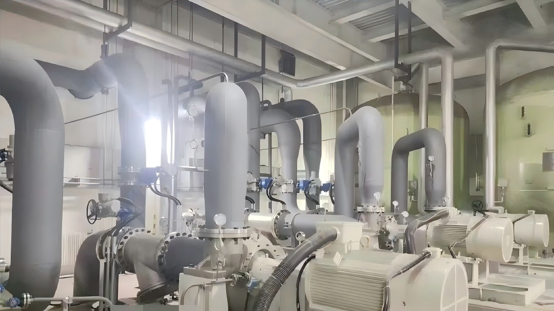
LEO solution
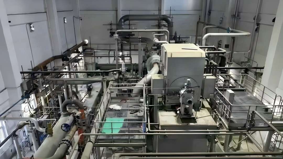
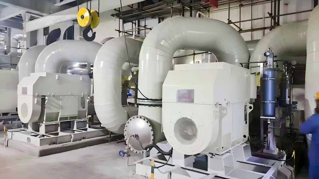
To address these challenges, LEO Pump Industry developed a comprehensive pump system solution tailored for the project, covering the entire process. The solution includes 31 core pump units such as the HR Series (BB2) heavy-duty petrochemical process pumps, OH2 single-stage cantilever pumps, and HY Series vertical pumps, establishing a stable, efficient, and reliable fluid distribution system for carbon capture technology.
1. Corrosion-resistant design to solidify the foundation of safe operation
For highly corrosive media like amine solutions, LEO employs standardized heavy-duty pumps at core absorption/desorption stations, integrated with high-performance materials and mechanical sealing technology. This design fundamentally eliminates leakage risks of hazardous substances, ensuring both intrinsic safety and long-term operational reliability.
2. Drive green and low-carbon operation with frequency conversion energy-saving technology
To meet the project's stringent energy efficiency requirements, LEO has equipped multiple high-power pump units with high-efficiency motors and variable frequency drive systems as standard. The variable frequency speed control precisely matches pump output to process demands, significantly reducing energy losses caused by traditional valve throttling. This enhances the system's overall energy efficiency and contributes to lowering the lifecycle costs of carbon capture.
3. Enhance project delivery quality through modular integration
For critical work sections, LEO provides modular skid-mounted pump system integration. This factory-prefabricated, tested, and integrated approach significantly reduces on-site installation uncertainties, ensuring operational accuracy, stability, and reliability of equipment while shortening construction timelines.
LEO Advantages
In this project, LEO's following strengths are highlighted:
★Full-scenario coverage capability
We provide end-to-end solutions spanning from large process pumps to precision dosing pumps, with unified design standards and equipment styles that dramatically reduce procurement and management cycles.
★Industrial-grade reliability standards
The core components of the Liou project utilize top-tier domestic and international brands, featuring high-efficiency motors designed to withstand extreme CCUS operating conditions.
★System Energy Efficiency Perspective
We go beyond single-pump solutions to deliver comprehensive system-level energy efficiency optimization packages, including motors and control systems, directly addressing customers' cost reduction pain points.
★Professional Technical Innovation
To address the specific requirements of carbon capture media and processes, this solution employs cavitation protection and multiple technical optimizations to fundamentally resolve the common challenges of cavitation and seal failure in carbon capture projects.

FLOW Towards The Future
Capturing 1.5 million tons of carbon dioxide annually is not only a numerical leap but also symbolizes China's pragmatic and resolute choice on the path of energy transition. It proves that through technological innovation, traditional coal power bases can also become pioneers of negative carbon actions. In this green panorama on the Loess Plateau, every pump operating steadily stands as a silent witness to the efficient conversion of energy and precise material delivery.
LEO is honored to participate in and contribute to this national demonstration project through the power of "Smart Flow." In the future, we will continue to focus on the fields of energy and chemical engineering, as well as energy conservation and environmental protection. With more efficient, reliable, and green fluid technology solutions, we will collaborate with partners to build a harmonious world where humans and nature coexist, contributing our expertise to this cause.