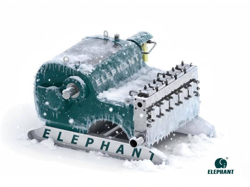
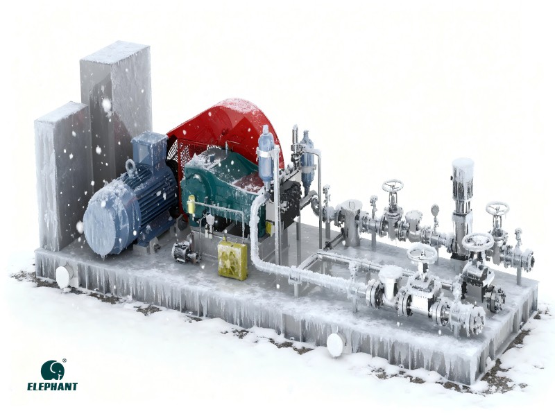
Maintenance of reciprocating pumps during cold seasons is crucial, primarily to prevent freezing and ensure normal operation in low-temperature environments, thereby avoiding failures and damage caused by cold weather. Specific measures include:
1. Thoroughly inspect whether the insulation measures applied to the pump body and piping are fully adequate. Conduct a comprehensive and meticulous inspection of all aspects, including insulation coverage and sealing integrity. If deficiencies are identified during the inspection, promptly add insulation layers or install heating cables as necessary. Adding insulation layers further enhances thermal insulation, reducing heat loss; installing heating cables actively provides heat to the pump body and piping, effectively preventing the freezing of liquids within the pipes.
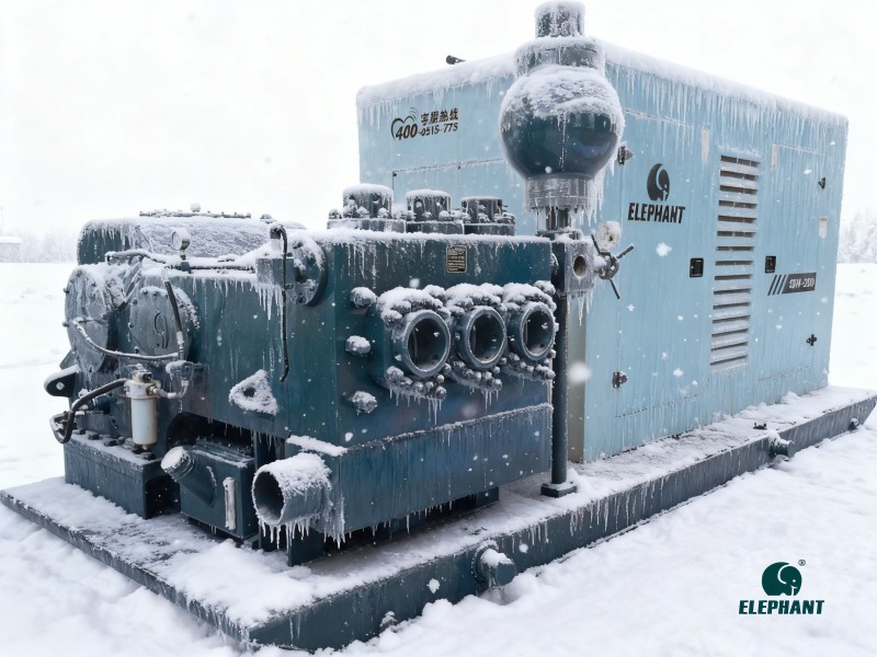
2. During the period when the equipment is shut down, all residual liquid remaining inside the pump chamber and pipelines must be completely drained. The primary purpose of this is to prevent these residual liquids from freezing in low-temperature environments. Once frozen, liquids expand, and the force generated by this expansion could potentially cause the equipment to rupture.
3. According to a pre-set fixed cycle, the pump equipment is activated for brief operational runs. During pump operation, the relative motion between its internal mechanical components—that is, mechanical movement—generates a certain amount of heat. This heat produced by mechanical motion is utilized to maintain the pump's internal temperature at a relatively stable and suitable level. The purpose of this is to effectively prevent pump components from becoming stiff due to low temperatures or other factors, ensuring the pump can continue to operate normally.
4. In relevant application scenarios, we can use antifreeze to replace conventional working fluids. Particularly under extreme low-temperature conditions, conventional working fluids may face the risk of solidification. Using antifreeze effectively prevents this from occurring, ensuring the fluid remains liquid and maintaining the normal operation of the entire system.
5. For critical components within the equipment—such as seals, valves, and piston rods that play vital roles—meticulous lubrication maintenance is essential. The primary purpose of lubricating these key components is to prevent material hardening under low-temperature conditions and to mitigate wear caused by increased friction between parts due to cold temperatures.
6. To ensure stable equipment operation and safe, orderly production, routine inspection efforts must be strengthened. During inspections, focus on the operational status of instruments such as pressure gauges and flow meters, as they provide real-time feedback on critical system parameters and are vital to normal system functioning. Inspection personnel must meticulously observe instrument readings and operational conditions with a professional mindset. Should any anomalies be detected—such as fluctuating display data or abnormal pointer movements—detailed records must be made immediately and prompt corrective action taken to prevent issues from escalating and impacting system performance.
Warning: If the equipment freezes, never use open flames to thaw it, as this may damage the pump body and pipes. Applying direct heat causes localized temperature spikes, leading to uneven heating of the pump or pipe materials. This can result in deformation, cracking, or even leaks, posing serious safety hazards. Instead, use gradual heating methods such as pouring warm water over the frozen area or applying uniform heat with a hot air device.
By following the above methods, you can significantly reduce the likelihood of reciprocating pumps malfunctioning during cold seasons, ensuring their smooth and safe operation. For any further questions regarding reciprocating pumps, feel free to contact the Elephant Machinery team at any time. We will provide the best service and solutions.