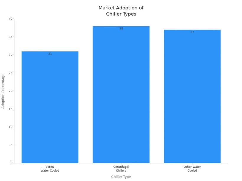
An ordinary motor will face a series of severe challenges in a vacuum environment. Without special design and treatment, it is likely to fail within a short period. Simply put, an ordinary motor cannot be used directly in a vacuum environment.
The main reasons and potential consequences are as follows:
Heat Dissipation Problem (The Most Critical Issue)
In Earth's Atmosphere: The motor generates heat during operation. Ordinary motors dissipate heat primarily through three methods:
Convection: Surrounding air flow carries heat away (this is the primary method).
Conduction: Heat is transferred to the mounting structure via the motor base.
Radiation: Heat is radiated outward as infrared radiation (accounts for a very small proportion at normal temperatures).
In a Vacuum: There is no air, so convective heat transfer completely fails. Heat dissipation can only rely on conduction and radiation.
Conduction becomes crucial but requires extremely large-area, tight contact between the motor and the mounting structure, along with the use of highly thermally conductive materials (e.g., thermal grease). This is very difficult to achieve perfectly in engineering.
Radiation is very inefficient at low temperatures.
Consequence: The motor will overheat drastically, causing internal temperatures to far exceed design limits. This can lead to melting of the insulation, demagnetization of permanent magnets, evaporation or solidification of bearing lubricant, and ultimately result in motor burnout or seizure.
Lubrication Problem
Ordinary Lubricants: Most greases or lubricating oils used in ordinary motors will, in a vacuum environment:
Rapidly Evaporate/Sublime: The boiling point is extremely low in a vacuum, causing liquid lubricants to rapidly turn into gas and evaporate, leading to dry running of the bearings.
Contaminate the Environment: The evaporated oil vapor can condense on nearby precision equipment, such as optical lenses or sensor surfaces, causing permanent contamination and functional failure. This is absolutely unacceptable for spacecraft.
Consequence: The bearings wear out or seize due to lack of lubrication in a short time, causing the motor to stop rotating.
Corona Discharge and Arcing (Especially Dangerous for High-Voltage Motors)
In Earth's Atmosphere: Air has a certain dielectric strength, preventing discharge between electrodes below a certain voltage.
In a Vacuum: Vacuum itself is an excellent insulator, but its insulating capability is closely related to electrode material and surface finish. In a vacuum, insulation between electrodes no longer relies on a medium but on the vacuum itself.
The problem is: At high voltages, motor windings—especially at points with minor insulation defects or sharp points—can cause residual gas molecules to ionize, easily leading to corona discharge or vacuum arcing.
Consequence: Continuous discharge can severely erode and damage the insulation material, eventually causing winding short circuits and motor failure.
Material Outgassing
Problem: Many materials used in the manufacturing of ordinary motors (such as plastics, paints, adhesives, ordinary wire insulation, etc.) absorb and dissolve gas molecules from the air. In a vacuum environment, these gases are slowly released, a process known as "outgassing."
Consequence: Similar to lubricant evaporation, these released gases can contaminate the entire vacuum system, which is fatal for scientific experiments requiring ultra-high vacuum or for space telescopes.
So, What Motors Are Used in Vacuum Environments?
To solve the above problems, engineers have developed motors specifically designed for vacuum environments. The main solutions include:
Special Heat Dissipation Design:
Strengthen conduction paths using highly thermally conductive metals (like copper) for components or heat sinks.
Design dedicated connection cooling plates with internal coolant to forcibly remove heat.
Increase the motor's operating temperature class using higher-grade insulation materials (e.g., Class H, Class C).
Vacuum Lubrication Technology:
Use solid lubricants such as molybdenum disulfide, PTFE, or graphite.
Use full ceramic bearings or specially treated metal bearings.
Vacuum-Compatible Materials and Insulation:
Select all structural materials with low outgassing rates.
Use special vacuum-compatible impregnating varnishes and potting materials for windings.
For high-voltage motors, special consideration must be given to insulation structure and processes to prevent corona discharge.
Therefore, if you need to use a motor in a vacuum environment (such as in space equipment, vacuum coating machines, particle accelerators, etc.), you must select a vacuum motor specifically designed and certified for vacuum use, and cannot directly use an ordinary motor.
In the "last mile" of cement production—the loading of bagged cement—we seem to be trapped in a persistent predicament.
Walk into any traditional cement plant's loading site, and you'll likely see this scene: billowing dust blurs visibility, workers wrapped in heavy protective suits and masks struggle to navigate between trucks and conveyor belts. This isn't just a matter of efficiency; it's a severe test of occupational health, environmental protection, and corporate costs.
The continuous rise in labor costs, increasingly stringent environmental regulations, and the relentless pursuit of operational efficiency have collectively propelled "fully automated loading" to the forefront of industry transformation. However, as we embrace automation with high hopes, we find that existing solutions on the market always fall short.
Today, we'll delve into why traditional automated loading solutions have consistently failed to truly "end" this industry ailment.
A Visual Comparison of Three Mainstream Solutions: The Ideal is Beautiful, the Reality is Harsh
The market has not been without attempts. Currently, mainstream automated cement loading solutions fall into three main categories, but each has its own significant technological hurdles. We have created the following diagram to clearly illustrate their core challenges:
Scheme type
Core Principles
Advantages
Fatal Flaw
Robotic loading arm
To mimic human operation, large industrial robots are used to grab and stack material bags.
It is highly flexible and can theoretically be adapted to various vehicle models.
The dust pollution is enormous: the grabbing and throwing actions can easily break the bags, causing explosive dust leaks.
Package loading head
Materials are sequentially dropped and stacked through multiple discharge ports and sliding trolleys.
The structure is relatively simple and the control logic is straightforward.
Maintenance nightmare: The equipment has a compact structure, extremely narrow maintenance space, and long downtime due to malfunctions.
High-sideboard solution
A top-loading system designed for standard vans.
Loading speed is fast, and dust control is acceptable.
Extremely poor adaptability: It cannot handle high-sided, flatbed, or modified vehicles, greatly reducing its practicality.
The pain points are immediately apparent.
Figure 1: Robotic arm loading truck – “Dust generator”
(When traditional robotic arms grab and throw cement bags, the resulting dust clouds engulf the entire work area, severely reducing visibility. This is not only pollution, but also a huge safety hazard and a significant waste of materials.)
(A high-sided truck is parked under traditional loading equipment; the Jeenar loading equipment lowers the load far below the sideboards, only 60cm from the bottom of the truck bed.)
The root cause of the predicament: What do we really need?
Looking at the above solutions, we find a common thread: they are all “patches and repairs” on the existing technological framework, failing to fundamentally understand and solve the core needs of the loading process. A truly qualified automated loading solution must simultaneously meet the following four points:
Environmentally friendly and dust-free: Suppressing dust at the source, protecting worker health, and meeting the environmental protection requirements of “green mountains and clear waters.”
Stable and efficient: High equipment reliability, convenient maintenance, and the ability to achieve continuous and stable operation 24/7, significantly improving delivery efficiency.
Widely adaptable: It must be able to easily handle the large number of non-standard vehicles present in the Chinese market, such as high-sided trucks, flatbed trucks, and agricultural vehicles.
High return on investment: Not only must it be affordable to buy, but also affordable to use and repair, with overall costs superior to manual labor teams.
Unfortunately, traditional robotic arms, stacking heads, and high-sided pallet solutions all have significant shortcomings on different sides of this "perfect quadrilateral."
The Solution: A Leap in Thinking from "External Stacking" to "Internal Operation"
So, where does the solution lie?
If existing solutions merely involve "airdropping" from outside the wagon, then no matter how sophisticated the movements, dust, bag breakage, and adaptability issues are unavoidable.
Gachn's answer is based on this fundamental leap in thinking: Why not operate inside the wagon?
This is precisely the design philosophy behind our innovative "in-carriage" automated loading system. It is no longer a simple "loading machine," but an intelligent, precise, and dust-free "in-carriage robot."
Direct Dust Control: Through a unique dust suppression design and gentle, precise stacking inside the wagon, dust from high-altitude drops and throwing is physically eliminated.
Direct Maintenance: A modular design makes maintenance of key components readily accessible, minimizing the Mean Time To Repair (MTTR).
Directly facing vehicle types: The innovative telescopic and rotating mechanism allows it to "penetrate" deep into the interiors of various high-sided and irregularly shaped truck bodies, achieving full coverage operation.
Conclusion: The industry's pain points are the starting point for our innovation. We deeply understand that on the journey of automated cement loading, there is no shortage of solutions, but a lack of solutions that truly "solve the problem."
Introduction: Are you still troubled by problems such as dust storms, the inability to automatically load high-sided trucks, and loading speeds falling short of expectations in the cement loading process? Traditional robotic arms and stacking head solutions, due to their inherent defects, have never provided a perfect solution. Today, Xiamen Gachn presents the world's first "In-Cargo" Intelligent Cement Loading Machine (ICO), which will let you witness a true revolution in loading.
"In-Cargo" is the core essence of our technology. It completely overturns the traditional method of "throwing" or "placing" bagged cement outside the truck bed, innovatively allowing the loading head to directly extend into the truck bed for low-position, precise stacking operations.
Simply put, our equipment "enters the truck bed" to work, while other equipment operates "outside the truck bed." This fundamental difference brings about a comprehensive performance leap forward.
(Traditional palletizing head/robotic arm operating outside the truck bed, generating significant dust and unable to handle high-sided trucks; Right: Gachn's "in-carriage" palletizing head extends deep into the truck bed for precise low-position palletizing.)
II. Three Core Advantages of "In-Carriage" Palletizing, Addressing Industry Pain Points
Advantage 1: Full Vehicle Compatibility, No Vehicle Can Hinder It
Pain Point: Most truck loading machines on the market cannot effectively handle high-sided trucks, resulting in a large number of vehicles still requiring manual loading, rendering automation impossible.
Our Solution: With its in-carriage palletizing head, our equipment can easily adapt to various vehicle types, from low-sided to extra-high-sided trucks. Through self-developed intelligent 3D scanning and palletizing algorithms, the system can automatically identify vehicle types and intelligently employ various palletizing modes such as horizontal, vertical, or a combination of horizontal and vertical palletizing, achieving a vehicle compatibility rate of over 90%.
(How Gachn equipment intelligently adjusts palletizing strategies for vehicles with different sideboard heights)
Advantage Two: High Efficiency and Dust-Free Operation, Locking in Dust at the Source
Pain Point: Traditional robotic arms' high-position bag throwing and high-position bag dropping are the main causes of dust pollution at the loading site.
Our Solution: The "in-cargo" design achieves low-position bag stacking. The drop difference between the bagged cement from the machine head to the bottom of the truck bed is minimal, fundamentally reducing dust generated by the impact of falling bags. Combined with a high-efficiency central dust collection system (which can utilize existing plant systems for modification), residual dust can be captured instantly, ensuring a clean and environmentally friendly loading site.
Advantage Three: High Speed and Stability, Efficiency Far Exceeding Expectations
Pain Point: Many traditional solutions advertise speeds that do not match actual speeds; the actual speed of robotic arms is often only 70-80 tons/hour, becoming a bottleneck for production capacity.
Our Solution: Gachn's "in-cargo" loading machine achieves a stable high-speed loading capacity of 100-120 tons/hour. We employ a distributed layout, ensuring stable and reliable mechanical structures with an extremely low failure rate, guaranteeing continuous and efficient equipment operation to truly meet the high-intensity shipping demands of modern cement plants.
III. More Than Just Equipment, a Smart Solution
The "in-carriage" intelligent loading machine integrates a 3D vehicle scanning system, intelligent palletizing algorithms, and a Schneider Electric high-end control system, achieving full automation from vehicle recognition and position correction to planned palletizing and precise execution. Drivers only need to swipe their cards and input information; the equipment completes all subsequent tasks, truly achieving unattended intelligent loading.
Conclusion: Choosing the Gachn "in-carriage" intelligent loading machine is not a simple equipment replacement, but a complete upgrade to the traditional loading model. It means higher efficiency, a better environment, wider applicability, and lower overall operating costs.
Are you eager to witness firsthand how "in-carriage" loading solves your practical problems?
Reverse osmosis pumps inject water into reverse osmosis membranes under high pressure, effectively filtering out dissolved salts, organic matter, microorganisms, and other impurities. The key lies in their ability to sustain stable high pressure conditions over extended periods, ensuring filtration efficiency and water purity. Designed for both durability and energy efficiency, these pumps maintain high performance during prolonged operation. Furthermore, their compact construction facilitates easy installation and maintenance, offering users significant operational convenience. This high pressure pump is specifically engineered for reverse osmosis (RO) systems, playing a vital role within the RO process. Its primary function is to provide stable and sufficient pressure throughout the system, counteracting osmotic pressure and driving water molecules through the semi-permeable membrane. To ensure long-term reliable operation, the internal structure of the reverse osmosis pump undergoes precision machining, offering excellent corrosion and wear resistance, capable of withstanding various complex water quality conditions.
1. Working Principle of Reverse Osmosis Pumps
Reverse osmosis pumps utilize the reciprocating motion of a plunger to pressurize and convey fluids. When the plunger retracts, negative pressure forms within the pump chamber, opening the inlet valve and drawing water into the chamber. As the plunger advances, the water within the chamber is compressed, causing pressure to rise rapidly. The outlet valve then opens, delivering the high pressure water stream to the reverse osmosis system. This operating mechanism enables the plunger pump to deliver stable high pressure output, making it highly suitable for applications requiring high pressure and low flow rates. Additionally, due to its simple structure and the use of high performance materials for critical components, the plunger pump demonstrates exceptional efficiency and reliability during operation. It maintains long-term stable performance even under harsh working conditions.
2. Why is the reverse osmosis pump the “heart” of the RO system?
The reverse osmosis pump occupies a central position within the RO system, with its performance directly impacting the operational effectiveness and stability of the entire system. Serving as the driving force propelling water molecules through the semi-permeable membrane, it not only determines water production efficiency but also plays a critical role in achieving water purity. If the RO system were likened to a living organism, the reverse osmosis pump would be its powerhouse heart, continuously supplying energy to the system. Should the pump malfunction, the entire system risks stalling or operating inefficiently, potentially leading to irreversible damage. Therefore, selecting a high-quality reverse osmosis pump is essential for ensuring the long-term, stable operation of the RO system. Furthermore, its reliability and adaptability determine whether the system can maintain high performance under varying operating conditions, further underscoring its indispensable role.
In summary, reverse osmosis pumps play an irreplaceable role in RO systems. Their pivotal position is reflected not only in providing essential pressure support but also in their ability to flexibly adjust output according to actual demand, ensuring the system consistently operates at optimal performance. Moreover, the high efficiency and stable performance of reverse osmosis pumps enable the entire RO system to operate continuously in diverse complex environments, delivering reliable water quality assurance to users. This robust adaptability makes them the preferred equipment for reverse osmosis systems across various industries, seawater desalination projects, and pharmaceutical applications, further cementing their pivotal role as the “heart” of the system. Elephant Machinery offers the optimal selection of reverse osmosis pumps and can also provide customized solutions tailored to your requirements. We welcome your inquiries.
The BOP test pump is a specialized device designed to evaluate the performance of blowout preventer (BOP) at wellheads. By simulating high pressure environments, it assesses the sealing integrity and reliability of BOP, ensuring their safe operation during oil and gas extraction. This test pump typically features high-precision pressure control and data acquisition capabilities, enabling real-time monitoring and recording of critical parameters throughout the testing process to provide reliable data for subsequent analysis.
1. Function
The BOP test pump simulates various pressure conditions to evaluate the performance of blowout preventers under different operational states. It serves as the final and most critical safety barrier against well blowouts. This equipment identifies potential leak points or weak links without damaging the machinery, enabling operators to perform timely maintenance and repairs. Additionally, it supports multiple test modes that can be flexibly adjusted to meet specific operational requirements, ensuring each test achieves the desired outcome. Water is typically used for testing instead of drilling mud because it is clean, incompressible, clearly displays pressure changes, and causes less damage to equipment. Through precise pressure regulation and stable output, the BOP test pump effectively enhances testing efficiency while reducing the risk of human error.
2. Features
Unlike other drilling pumps (such as mud pumps), the BOP test pump is specifically designed for testing operations. Its design emphasizes practicality and reliability, featuring robust adaptability to ensure normal operation under harsh environmental conditions. The primary focus is on generating extremely high pressure rather than large-volume fluid transfer, resulting in lower flow rates. Its compact structure facilitates transportation and installation, making it suitable for diverse field applications. Manufactured using advanced materials and technologies, the equipment ensures long-term durability while reducing maintenance frequency and costs. Additionally, it incorporates multiple safety protection mechanisms to effectively prevent accidents caused by operational errors or unexpected incidents, providing enhanced safety assurance for field operations.
3. Application
BOP test pumps find extensive applications across the oil and gas industry. They are commonly deployed on drilling rigs, onshore wells, and offshore production facilities to conduct periodic inspections and performance verification of blowout preventers. This equipment enables operational teams to perform comprehensive performance assessments before equipment commissioning or during routine maintenance, ensuring compliance with safety standards. Additionally, BOP test pumps can adapt to testing demands in extreme environments, such as high temperatures, high pressures, or corrosive conditions, thereby safeguarding safe operations under complex working conditions. In practical applications, they not only help users meet industry regulatory requirements but also optimize overall operational workflows, reduce downtime caused by equipment failures, and enhance production efficiency.
The BOP test pump is a specialized piece of equipment primarily used for conducting high pressure seal integrity tests on critical well control devices such as blowout preventers. Within the oil and gas industry, the role of the BOP test pump cannot be overlooked. It not only performs initial performance verification on newly installed blowout preventers but also enables periodic inspections after equipment operation to ensure it remains in optimal condition. Elephant Machinery remains committed to providing customers worldwide with convenient, reliable, efficient, and intelligent reciprocating pump products. We offer high-quality BOP test pumps, including high pressure pumps and pressure test pumps.
Computer Numerical Control (CNC) machines have become the foundation of modern manufacturing, enabling precise, automated, and efficient machining processes. They are used across various industries, including automotive, aerospace, electronics, and general engineering, to produce parts with high accuracy and consistency.
Understanding the various types of CNC machines is crucial for selecting the appropriate equipment for specific production requirements. Each category—such as milling, turning, drilling, grinding, and cutting machines—serves distinct purposes and offers unique advantages in terms of precision, speed, and material compatibility.
What Is a CNC Machine?
A CNC machine (Computer Numerical Control machine) is an automated tool that uses computer programming to control machining operations with high precision. Instead of being manually operated by a machinist, the CNC system follows coded instructions—often written in G-code—to move cutting tools or workpieces along defined paths.
CNC machines are widely used to perform complex manufacturing tasks such as milling, turning, drilling, and grinding, allowing manufacturers to produce parts with exceptional accuracy, repeatability, and speed. Each movement, tool change, and feed rate is controlled automatically, ensuring consistent quality across large production runs.
The concept of CNC machining evolved from traditional manual control systems in the mid-20th century, when punched tape and numerical codes were first used to automate metal cutting. Today, CNC technology integrates advanced control systems, sensors, and even AI to enhance process stability and efficiency.
In modern factories, CNC machines are not limited to metal cutting. They are also applied to plastics, composites, ceramics, and wood, making them indispensable across industries such as automotive, aerospace, medical, and electronics manufacturing.
In essence, CNC machines have transformed the way manufacturers approach precision engineering—bridging the gap between human craftsmanship and digital automation.
Complete List of CNC Machines
CNC machines come in a wide variety of types, each designed for specific machining operations and material requirements. They differ in structure, tool configuration, and the type of motion they perform—linear, rotary, or a combination of both. Below is a comprehensive list of the most common CNC machine types, along with their main functions and typical applications.
Type of CNC Machine
Main Function
Common Applications
CNC Milling Machine
Removes material using rotating cutting tools along multiple axes (X, Y, Z)
Molds, dies, precision parts, metal housings
CNC Turning Machine (Lathe)
Rotates the workpiece while a stationary cutting tool shapes it
Shafts, bushings, fasteners, cylindrical parts
CNC Drilling Machine
Creates holes of precise depth and diameter using automated drill bits
Engine blocks, plates, and mechanical components
CNC Grinding Machine
Uses abrasive wheels for surface finishing and precision tolerances
Enlarges or finishes existing holes with high accuracy
Engine cylinders, large castings, heavy machinery parts
CNC Plasma Cutting Machine
Cuts through electrically conductive materials using a high-temperature plasma arc
Sheet metal fabrication, automotive frames
CNC Laser Cutting Machine
Uses focused laser beams for precise, high-speed cutting and engraving
Thin metal sheets, electronics, signage, fine components
CNC EDM (Electrical Discharge Machine)
Removes material by electrical discharges between the tool and workpiece
Hard materials, molds, dies, aerospace components
CNC Router
Cuts and shapes softer materials using rotary tools
Wood, plastic, foam, composite parts
CNC Engraving Machine
Used for detailed engraving, marking, and fine pattern cutting
Jewelry, mold marking, nameplates, logos
CNC Machining Center
A multifunctional system combining milling, drilling, tapping, and tool changing
Precision components, high-volume manufacturing
5-Axis CNC Machine
Offers advanced multi-directional machining for complex geometries
Aerospace, medical implants, turbine blades
CNC machines can range from simple 2-axis models to complex 5-axis or multi-tasking machining centers that integrate turning and milling in one setup. The right type depends on the required precision, material type, production volume, and part complexity.
CNC Milling Machines – The Backbone of Precision Machining
Among all CNC machine types, CNC milling machines are considered the most versatile and widely used in modern manufacturing. They operate by rotating cutting tools along multiple axes—typically X, Y, and Z—to remove material from a stationary workpiece and shape it into the desired geometry.
CNC milling machines are classified mainly into vertical and horizontal configurations:
Have a horizontally positioned spindle, allowing gravity-assisted chip removal and better efficiency in machining large or heavy parts.
Advanced models, such as 5-axis CNC milling machines, provide additional rotational movements, enabling complex surface machining in a single setup. This reduces setup time, increases accuracy, and is especially valuable for industries such as aerospace, medical device manufacturing, and high-precision mold making.
Key performance factors for CNC milling machines include spindle speed, feed rate, travel distance, and tool capacity. Modern systems are often equipped with automatic tool changers (ATC) and high-speed spindles that support simultaneous multi-tool operations.
CNC Turning Machines – Precision in Round Components
CNC turning machines, commonly known as CNC lathes, are designed for producing rotationally symmetrical parts with exceptional accuracy. Unlike milling machines, which move the cutting tool around a stationary workpiece, CNC turning machines rotate the workpiece while a stationary cutting tool removes material. This makes them ideal for manufacturing shafts, bushings, fasteners, and cylindrical components that require high surface finish and tight tolerances.
Modern CNC turning machines are typically categorized by the number of controlled axes and their machining capabilities:
2-Axis CNC Lathes:
These are the standard type, featuring two controlled axes—X and Z. They perform essential operations such as facing, turning, threading, and grooving with high efficiency.
3-Axis and C-Axis Lathes:
Include an additional C-axis, enabling the spindle to be indexed or continuously rotated for basic milling, drilling, and tapping operations.
Designed for complex, multi-operation machining in one setup, reducing the need for part repositioning and manual handling.
Swiss-Type CNC Lathes:
Features a sliding headstock and guide bushing system, allowing ultra-precise machining of small-diameter parts for medical, electronics, and watchmaking industries.
Equipped with advanced CNC control systems and automatic tool changers, modern turning centers deliver outstanding precision, speed, and repeatability. They are widely used in automotive, aerospace, and hydraulic manufacturing, where performance and consistency are critical.
CNC Drilling, Boring, and Grinding Machines
Beyond milling and turning, CNC drilling, boring, and grinding machines play vital roles in achieving precision holes, fine tolerances, and high-quality surface finishes. Each type serves a specific purpose in the machining process and is indispensable for complete manufacturing solutions.
CNC Drilling Machines
CNC drilling machines are designed to create accurate holes with controlled depth and diameter. They can be equipped with multiple spindles or turret heads, allowing several holes to be drilled simultaneously. Advanced models support tapping, countersinking, and reaming operations within a single cycle. These machines are commonly used in automotive, aerospace, and machinery component production, where precise alignment and hole consistency are essential.
CNC Boring Machines
Boring machines are used to enlarge and finish existing holes with extreme accuracy. CNC boring centers often handle large workpieces such as engine blocks, machine bases, and heavy castings. Horizontal boring machines, in particular, offer superior stability and are ideal for deep-hole machining. Their computer-controlled feeds and spindle movement ensure exact dimensional tolerances, even in large-scale production.
CNC Grinding Machines
CNC grinding machines employ abrasive wheels to achieve fine surface finishes and tight dimensional accuracy. Depending on configuration, they can perform surface grinding, cylindrical grinding, or internal grinding. These machines are essential for producing tools, bearings, dies, and precision components, where micron-level accuracy is required.
Together, CNC drilling, boring, and grinding machines form a critical part of the machining ecosystem—delivering accuracy, consistency, and high-quality surface integrity for modern industrial manufacturing.
5-Axis CNC Machines
A 5-axis CNC machine represents the most advanced form of CNC machining technology. It can move a tool or a part along five different axes simultaneously — the traditional X, Y, and Z linear axes, plus two additional rotary axes (A and B). This configuration allows the tool to approach the workpiece from virtually any direction.
5-axis machines are used for complex geometries and high-precision components, such as those found in aerospace, medical, and automotive industries. They are ideal for parts that require machining on multiple faces or have intricate curves that would otherwise need multiple setups.
Advantages:
Capable of producing highly complex and contoured surfaces
Reduces setup time — multiple sides can be machined in one pass
Improves accuracy by minimizing repositioning errors
Enhances surface finish due to smoother tool movements
Common applications:
Turbine blades and impellers
Aerospace structural parts
Artificial joints and medical implants
High-performance automotive components
CNC Machine Components
A CNC machine is made up of several key components that work together to ensure precision, speed, and reliability. Understanding these parts helps users operate, maintain, and troubleshoot their machines more effectively.
1. Control Panel (CNC Controller)
The CNC controller is the “brain” of the machine. It interprets the G-code instructions from the program and sends precise commands to the motors and actuators.
Functions: program input, coordinate control, and error detection
Example: Fanuc, Siemens, Mitsubishi, or Heidenhain controllers
2. Machine Bed
The machine bed serves as the foundation of the CNC machine. It supports all other components and absorbs vibrations during machining to maintain accuracy.
Usually made of cast iron or mineral composite for high stability and rigidity.
3. Spindle
The spindle is the rotating component that holds and drives the cutting. tool. Its performance directly affects machining speed and surface finish.
Can be belt-driven, gear-driven, or direct-drive (built-in) type.
High-speed spindles are essential for precision machining of aluminum and composite materials.
4. Tool Changer
The automatic tool changer (ATC) enables the machine to switch between different cutting tools automatically, increasing efficiency and reducing downtime.
Common types: drum-type and chain-type tool changers.
Typical capacity: 16 to 60 tools, depending on the machine size.
5. Axis Drive System
The axis drive system controls movement along each axis (X, Y, Z, and others).
Ball screws and linear guideways ensure smooth and precise positioning.
Servo motors or stepper motors drive the axes with feedback control.
6. Worktable
The worktable is where the workpiece is mounted, often using fixtures, vises, or clamps.
Can move in multiple directions depending on the machine type.
In 5-axis machines, the table may tilt or rotate for multi-face machining
7. Coolant and Lubrication System
These systems maintain temperature stability and prevent tool wear.
Coolant removes heat and chips from the cutting area.
Lubrication ensures the smooth movement of mechanical components.
How Does a CNC Machine Work?
A CNC machine operates by following computerized instructions to automate the machining process. The process starts with a digital design, usually created in CAD (Computer-Aided Design) software. This design is then converted into G-code or M-code, which serves as the machine's instruction set.
Step 1: Programming and Setup
The operator loads the part design into the CNC controller.
Material is fixed on the worktable using clamps, vises, or fixtures.
The appropriate cutting tool is installed in the spindle or tool turret.
Step 2: Machine Motion
The CNC controller interprets the G-code commands to control each axis of the machine.
Linear axes (X, Y, Z) move the tool or workpiece precisely, while rotary axes (A, B, C) allow complex orientation in multi-axis machines.
The servo motors and ball screws ensure smooth, accurate, and repeatable movements.
Step 3: Material Removal
The cutting tool engages the workpiece, removing material according to the programmed path.
Spindle speed, feed rate, and depth of cut are controlled automatically to maintain quality and prevent tool wear.
For multi-operation machines, the automatic tool changer (ATC) switches tools as needed without stopping the program.
Step 4: Monitoring and Feedback
Modern CNC machines have sensors and feedback systems to monitor spindle load, tool wear, and axis position.
The controller adjusts movements in real-time to ensure precision and repeatability.
By combining digital programming, precise mechanical motion, and automated tool handling, CNC machines can produce high-precision components efficiently, consistently, and with minimal human intervention—making them indispensable in modern manufacturing.
Applications of CNC Machines in Different Industries
CNC machines are widely used across various industries due to their precision, efficiency, and versatility. Understanding their applications helps manufacturers and engineers choose the right machine type for their production needs.
1. Aerospace Industry
CNC machines produce turbine blades, engine components, and structural airframe parts.
High-speed and multi-axis CNC machining ensures tight tolerances and complex geometries required for safety-critical aerospace components.
2. Automotive Industry
Commonly used for engine blocks, crankshafts, gears, and custom vehicle parts.
CNC milling and turning machines improve production speed while maintaining consistent quality across mass production lines.
3. Electronics and Electrical Equipment
CNC routers and small milling machines are used for circuit boards, aluminum housings, and precision enclosures.
The high accuracy of CNC ensures reliable fits and smooth finishes, essential for electronic assemblies.
4. Medical and Healthcare
CNC machining is critical for implants, surgical instruments, and prosthetic components.
Machines with 5-axis or multi-axis capabilities can produce complex organic shapes with micron-level precision.
5. General Manufacturing and Tooling
CNC machines support mold making, die production, and custom mechanical parts.
Surface grinding, drilling, and milling capabilities allow manufacturers to produce high-precision tools and components efficiently.
6. Energy and Heavy Machinery
CNC boring and turning machines handle large castings, turbine components, and hydraulic equipment.
High stability and automated control ensure consistent accuracy for heavy-duty industrial parts.
Conclusion
CNC machines have transformed modern manufacturing, offering precision, automation, and versatility. From milling and turning to drilling, grinding, and multi-axis machining, each type serves specific purposes across industries like aerospace, automotive, electronics, and medical.
Understanding the list of CNC machines and their applications helps manufacturers select the right equipment for their production needs. With advances in AI, IoT, and automation, CNC machines now deliver higher efficiency, accuracy, and the ability to handle complex part geometries.
By choosing the right CNC machine, manufacturers can improve productivity, maintain quality, and stay competitive in 2025.
The combination of "cryogenic" and "biomedical" often points to high-precision, advanced, and high-value technologies. Here, "cryogenic" typically refers to deep cold environments ranging from -40°C to -196°C (liquid nitrogen temperature) or even lower.
Standard motors face severe challenges in low-temperature environments:
Material Embrittlement: Lubricants solidify, seals fail, plastic components become brittle.
Performance Degradation: Magnet properties change, potentially leading to torque loss and reduced positioning accuracy.
Condensation Issues: When a motor operating in a cold environment returns to room temperature, moisture condenses on its surface, causing short circuits and corrosion.
Therefore, cryogenic stepper motors are specially designed and manufactured products with the following characteristics:
Special Lubrication: Uses specialized greases that maintain lubricity at low temperatures or solid lubricants.
Material Selection: Employs materials with stable mechanical properties at low temperatures, such as specific stainless steels, low-temperature plastics, and composites.
Thermal Design: Accounts for thermal expansion and contraction of materials under extreme temperature variations to prevent structural damage.
Anti-Condensation Treatment: May involve measures like vacuum encapsulation or filling with inert gas.
Main Application Areas of Cryogenic Motors in the Biomedical Industry,Here are several core and rapidly growing application scenarios:
1. Automated Biobanks
This is the most typical and widespread application. Biobanks are used for the long-term storage of biological samples like blood, tissue, DNA, and cells, typically preserved in -80°C ultra-low freezers or -196°C liquid nitrogen tanks.
Application Scenario: In robotic arms or conveyor systems inside ultra-low freezers or liquid nitrogen tanks.
Motor Role: Drives robotic arms for picking, storing, organizing, and retrieving samples.
Technical Requirements:
High Reliability: If the system fails, repairs require warming the entire storage environment, potentially causing the loss of millions of samples with immense cost. Therefore, motors must be extremely reliable.
Precise Position Control: Needs to accurately locate individual test tubes or cryoboxes within dense sample racks.
Continuous Cryogenic Operation: Motors must operate stably 24/7 in deep cryogenic environments without "seizing" or experiencing insufficient torque.
2. Cryogenic Transfer/Dispensing Systems
In pharmaceutical or biological reagent production processes, liquids or semi-fluids need dispensing, capping, sealing, etc., in low-temperature environments.
Application Scenario: Installed on automated production lines within freezing chambers or glove boxes.
Motor Role: Drives pumps, valves, lead screws, and timing belts to achieve precise volume dispensing and container transfer.
Technical Requirements:
Smooth Motion: Avoids splashing of precious biological materials or bubble generation due to jerky movements.
Corrosion Resistance: May be exposed to trace amounts of chemical reagents or biological vapors.
3. Medical Cryogenic Centrifuges
Certain specialized biological separation processes (e.g., separation and purification of cells, viruses, proteins) need to be performed at low temperatures to preserve biological activity.
Application Scenario: Driving the lid open/close mechanism of centrifuges, or driving rotor balancing systems in large centrifuges.
Motor Role: Provides stable, reliable linear or rotary motion, ensuring automation of operations within cryogenic laboratories.
Technical Requirements:
Rapid Response & High Torque: Especially for lid locking mechanisms, sufficient torque and fast action are required.
Low Vibration: Any excess vibration affects centrifuge balance and sample quality.
4. Cryogenic Microscopy and Imaging Systems
To observe dynamic processes or structures of biological samples (e.g., live cells, tissue sections) at low temperatures, microscopes equipped with cooling stages are used.
Application Scenario: Integrated into the movement control system of the cryogenic sample stage.
Motor Role: Drives precision X-Y-Z movement of the stage, focus adjustment, and objective turret switching.
Technical Requirements:
Ultra-High Precision & Resolution: Microstepping control of the motor must be very fine to achieve sub-micron positioning.
Minimal Heat Generation: Heat generated by motor operation must be minimized to avoid affecting the temperature stability of the sample stage and the sample itself.
No Magnetic Interference: Some imaging techniques (e.g., MRI) are highly sensitive to electromagnetic interference, potentially requiring non-magnetic or low-magnetic models.
Cryo-EM is a revolutionary technique in structural biology. Its sample preparation process needs to be performed in a vitrified state at liquid nitrogen temperatures.
Application Scenario: In automated plunge freezers or cryo-milling instruments.
Motor Role: Controls critical parameters like the plunge speed of the sample rod, contact force and time of blotting paper, etc.
Technical Requirements:
Extremely High Repeatability: The success rate of sample preparation highly depends on the repeatability of each step.
Compatibility with High & Low Speeds: Requires both rapid plunging and fine micro-adjustment movements.
Future Trends:
With the rapid development of precision medicine, gene therapy, and biopharmaceuticals, the demand for automated and intelligent cryogenic processing equipment is growing increasingly strong. As the core drive component of this equipment, the precision, reliability, integration, and intelligence (e.g., built-in sensor feedback) of cryogenic motors will continue to improve to meet more demanding future application requirements.
Yes,cast iron round frying skillet pans are safe to use and are actually known for being extremely durable and versatile. They’re great for high-heat cooking, searing, frying, and even baking. However, there are a few things to keep in mind to ensure they stay in good condition and are safe:
Proper Seasoning: Cast iron pans need to be properly seasoned to maintain their non-stick surface and prevent rust. A well-seasoned pan can handle high temperatures and adds flavor to food. If your pan starts to rust or the seasoning wears off, you’ll need to reseason it.
Handling with Care: Cast iron can get extremely hot, so always use an oven mitt or pot holder when handling the pan to avoid burns.
Avoiding Abrasive Cleaning: After use, avoid harsh scrubbing or soaking the pan, as it can damage the seasoning. A little hot water and a stiff brush are usually enough. If you do need to clean it more thoroughly, you can reapply some oil to help maintain the seasoning.
Preheating: Cast iron pans should be preheated slowly, especially if they are cold. Rapid temperature changes can cause them to crack or warp.
Storing Properly: After use, make sure the pan is completely dry before storing it to avoid rusting. You can also apply a thin layer of oil to prevent moisture from getting in.
So, if you take care of it, a cast iron round frying pan is not only safe to use, but it can last for generations!
When evaluating a valve bag making machine, visible parameters like maximum speed and daily bag production are certainly attractive. However, what truly determines your return on investment is often the quality unseen on the specifications sheet—will it remain as stable as ever after three years? Are its long-term failure rate and maintenance costs controllable?
We firmly believe that an excellent machine is the result of a combination of top-tier genes (core components), a superior framework (manufacturing process), and reliable support (professional service). Today, let's set aside marketing rhetoric and delve into the intricacies of the FK008 to understand the root of its exceptional reliability.
I. Core Component Matrix: A Powerful Alliance of Top Global Brands
The cornerstone of the FK008's performance stems from our uncompromising selection standards for core components. We firmly believe that only first-class input can guarantee first-class output.
System Category
core components
Brand selection (example)
The value it brings to you
Electrical Control
PLC, servo motor, human-machine interface
Schneider (France)
The system's brain provides precise commands, exhibits extremely high stability, and possesses strong anti-interference capabilities.
Pneumatic Systems
Solenoid valve, cylinder, air conditioning unit
SMC (Japan) / Festo (Germany)
Quick and reliable operation, long service life
Transmission and Mechanical
Servo planetary gear reducer
SHIMPO (Japan)
Ensure transmission accuracy and stability under high speed and high load, and eliminate vibration.
Correction system
BST (Germany) / FIFE (USA)
Ensuring that the roll material is always aligned is fundamental to producing a perfect bag shape.
rolling bearings
NSK (Japan) / NTN (Japan)
Extremely low friction and wear ensure smooth and precise long-term operation of the equipment.
Why is this so important? These brands, proven in harsh global industrial environments, signify longer lifespans, higher operational precision, and lower failure rates, fundamentally ensuring the continuity and predictability of your production.
II. Manufacturing Process Highlights: The Essence Lies in the Details
High-quality components require sophisticated manufacturing processes for perfect integration. At Gachn's factory, we pay attention to every detail that can affect equipment lifespan and stability:
**Key Structural Component Reinforcement:** Core transmission and load-bearing components undergo heat treatment, significantly improving the strength, hardness, and toughness of the steel, effectively resisting deformation and fatigue.
**Comprehensive Surface Protection:** After machining, parts undergo rigorous surface treatments (such as chrome plating, phosphating, and powder coating), greatly enhancing their wear and corrosion resistance, adapting to various workshop environments.
**Lean Assembly Standards:** Our assembly engineers follow strict operating instructions to ensure that the torque of every bolt, the sealing of every air passage, and the coaxiality of every transmission component are optimal.
(Images showcasing meticulous installation by workshop engineers, laser cutting, and welding details demonstrate the rigorous manufacturing process.)
III. Professional Complete Line Services: From Single Machines to Turnkey Projects
We understand that you need more than just a bag-making machine; you need a complete solution that consistently produces high-quality products. Gachn Group, with its strong integration capabilities, provides you with:
* Scientific Complete Line Planning: From yarn drawing, circular weaving, coating to bag making, we offer end-to-end equipment and reasonable production capacity design, ensuring seamless integration and maximum efficiency.
* Strong Project Delivery Capabilities: We provide turnkey projects from layout design, installation and commissioning to personnel training, saving you time and effort and enabling rapid production.
IV. Service and Commitment: Ensuring Your Investment is Worry-Free
Choosing Gachn means gaining a long-term, reliable partner. We promise:
* Warranty Commitment: A 12-month warranty on the entire machine.
Ongoing Support: We offer up to 3 years of free upgrades to the control system software and remote technical support.
Professional Training: We dispatch experienced engineers to provide on-site installation, commissioning, and operation and maintenance training, ensuring your team can operate the equipment independently and proficiently.
Ultimate Action Call: Choose Long-Term Stable Production Guarantee
An FK008 valve bag making machine is the culmination of over 200 patents, an integrated platform of top-tier global components, and Gachn Group's ultimate interpretation of "reliability."
It is ready to become the most robust and reliable link in your production line.
Ensuring the reliability of vacuum motors (typically referring to motors that can operate stably under pressures below 10^(-2) Pa) in high-vacuum environments is a systematic project that requires strict control across multiple aspects, including material selection, structural design, manufacturing processes, and testing verification. Below are the key measures to ensure the reliability of vacuum motors, divided into several core layers:
Layer 1: Material Selection and Treatment – The Core of the Core
In high-vacuum environments, material outgassing is the primary issue. The released gases can not only contaminate the vacuum system but their condensates may also cause critical failures such as short circuits and lubrication failure.
Low Outgassing Materials:
Structural Materials: Prefer stainless steel (e.g., 304, 316L), oxygen-free copper, and aluminum alloys (requiring special surface treatment to reduce porosity). Absolutely avoid materials with high volatility or outgassing rates, such as plastics, rubber, ordinary paint, zinc, and cadmium.
Insulation Materials: Use vacuum-compatible insulating materials, such as polyimide (Kapton), polytetrafluoroethylene (PTFE), ceramics, and specialty epoxy resins. These materials are cured at high temperatures and have very low outgassing rates.
Magnetic Materials: Permanent magnets like neodymium iron boron may be unstable in high-vacuum environments, undergoing "vacuum volatilization," which leads to magnetic performance degradation. They must be coated with protective layers, such as nickel, zinc, or epoxy resin, and the coating must be dense and non-porous.
Material Pretreatment:
All materials should be rigorously cleaned before assembly to remove contaminants such as oil stains, fingerprints, and dust. Common processes include ultrasonic cleaning (using high-purity solvents like acetone and ethanol) and deionized water rinsing.
For critical components, vacuum baking may be necessary, which involves heating the materials in a vacuum environment at temperatures higher than the operating temperature for an extended period to accelerate the release of internal and surface-adsorbed gases.
Layer 2: Special Structural Design
Reducing Internal Cavities and Traps:
The motor design should minimize internal dead spaces and narrow gaps, which can act as "reservoirs" for gases and slowly release them. Common methods include using solid shafts and filling with epoxy resin.
All gaps and threaded connections should be designed to facilitate gas discharge.
Thermal Management Design:
In a vacuum, there is no air convection, making motor heat dissipation extremely challenging. Heat transfer primarily relies on radiation and conduction.
The design must be optimized to enhance heat conduction paths. For example, using materials with high thermal conductivity, increasing the contact area with the mounting base (cold plate), or even integrating cooling channels (for water or liquid nitrogen) inside the motor housing.
Precisely calculate the motor's thermal load to ensure its temperature rise in a vacuum remains within acceptable limits.
Preventing Cold Welding and Lubrication:
In ultra-high vacuum environments, clean metal surfaces may cold weld (adhere in a cold state), causing moving parts to seize.
Lubrication is one of the biggest challenges for vacuum motors. Ordinary greases will rapidly volatilize and contaminate the entire vacuum system.
Solid Lubrication: Use materials such as molybdenum disulfide, graphite, or PTFE. However, note that graphite's lubricity depends on adsorbed water vapor, and its performance may degrade in ultra-high vacuum.
Hard Coating Lubrication: Such as diamond-like carbon films.
Precious Metal Lubrication: Soft metals like gold and silver, which are less prone to oxidation, offer good lubrication in vacuum environments.
Specialized Space-Grade Lubricants: Such as perfluoropolyether or alkyl naphthalene synthetic oils, which are highly purified and have extremely low vapor pressure.
Layer 3: Manufacturing and Assembly Processes
Cleanroom Environment:
The entire motor assembly must be carried out in a high-grade cleanroom to prevent contamination from dust and fibers.
Welding Instead of Thread Locking Agents:
Use vacuum-compatible welding methods such as TIG welding or electron beam welding to seal the housing and connect wires. Avoid using thread-locking agents or sealants that produce volatile substances.
Lead Wire and Sealing:
The power and signal wires exiting the vacuum chamber are critical leakage points. Vacuum feedthroughs must be used, which employ ceramic-metal sealing technology to ensure absolute airtightness.
Layer 4: Testing and Verification
This is the final step to verify whether all design and process requirements are met.
Ground Simulation Testing:
Vacuum Level Testing: Place the motor in a vacuum chamber simulating its working environment, pump it to high vacuum (or even ultra-high vacuum), and operate it for an extended period while monitoring changes in vacuum levels to evaluate its total outgassing rate.
Life Testing: Conduct long-term start-stop, acceleration-deceleration, and continuous operation tests in a vacuum environment to assess its mechanical lifespan, lubrication longevity, and long-term stability of insulation performance.
High and Low-Temperature Cycle Testing: Simulate temperature changes in space or scientific equipment to verify the thermal compatibility of motor materials and structures, as well as the performance of lubricants at different temperatures.
Outgassing Product Collection Testing: Use quartz crystal microbalances or mass spectrometers to analyze the gas components released by the motor and identify contamination sources.
Summary
Ensuring the reliability of vacuum motors in high-vacuum environments is a closed-loop quality control system that runs through the entire process of design, material selection, manufacturing, and testing. The core guiding principles are:
Minimizing outgassing to the extreme: Achieved through low-outgassing materials, vacuum baking, and clean assembly.
Effectively addressing heat dissipation: Achieved by optimizing heat conduction and radiation paths.
Reliably achieving lubrication: Accomplished by selecting appropriate solid or specialized liquid lubrication solutions.
Rigorously verifying performance: Validated through ground simulations of all harsh operating conditions.
For highly demanding applications (such as spacecraft or particle accelerators), every detail is critical, and any minor oversight could lead to the failure of the entire mission.